
PM3-MBA Series Manual and Installation Guide

Copyright© 2012, Fieldstone Products, LLC. Fieldstone Products, LLC reserves the right to make changes in the product a t any time,
without notification
WARN ING
-
Avoid Possible Injury or Death
120 VAC
is present. This Converter/Charger is de signed to convert
120 VAC
to
12 VDC.
It also provides low voltage
power for charging on-board
12 VDC
batteries. The SRV series Converter/Ch arger is a "switch m ode" type and is
designed to be maintenance-free with no user serviceable components. The Converter/Charger power output is "current
limiting"
by design.
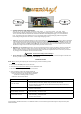
The Converter/Charger is integrated with a
120 VAC
and
12 VDC
Distribution Pa nel that allows easy installation and
centralizes all power connections. Stab type AC breakers with branch circuits are used. The DC fuse block ha s individually
fused branch circuits. The Converter/Char ger can easily be removed without removing the Distribution P anel wiring.
1.
DISCONNECT RV D C POWE R.
Disco nnect the RV battery POS (+) wire at the battery end before connecting this
Convert er/Ch arger and Distribution Panel to any RV w iring.
2.
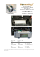
LOCATION.
The Main Board Assembly is mounted in the bottom compartment of the Power Distribution Panel cabinet.
3.
MOUNTING.
Flanges with holes are provided for ease of mounting using standard fasteners.
4.
ELECTRICAL REQUIREMENTS.
A
120 VAC
with 30 Amp sour ce, preferably a separate breaker, is requir ed to supply power.
5.
ELECTRICAL CONNECTIONS.
Be sure to tighten all connections securely . A loose connection can quickly cause termin als
and wires to o verheat . Review unit labels for recommended te rminal torque values.
6. THE FAN WILL NOT RUN ALL THE TIME. THE FAN RUNS ONLY WHEN NEEDED.
7. All PM3 Products must be installed by a certified electrician.
WARN I NG
-
Avoid Possible Injury or Deathl
120 VAC
Connection - First confirm that the
120 VAC
power source AC circuit breaker(s) are in the [OFF] position.
DO NOT
turn on AC circuit break ers un til ins tallation is complete. Connect the Neutral (white) wire to the N eutral terminal block (top left),
the Line (black) wire to the appropriate circuit breaker and the Ground (green-yellow) wire to the chassis terminal block (side
left).
12 VDC
Wi ring- It is im po rtant to use the correct wire gauge for the specific model
120 VAC
to
12 VDC
Convert er/Charger
selected. A s an example, the model PM4B-55-MBA is a 55 Amp Converter/Charger that requires at least 10 AWG wire.
Connect the positive (Blue) and negative (White) wires to the same t erminals where the old unit positive (Red) and negati ve
(White) wires were removed. The Converter/ Charger limits overall current output. However, with or without output current limits
on the
Converter/ Charger un it, all electrical connect ions mu st comp ly with the appropriate NEC codes.
SAFTEY ALERT!
FOR YOUR SAFETY, READ ALL INSTRU CTIONS BEFORE INSTALLATION AND OPERATION.
INSTALLER:
Provi de these instructions to the end user or consumer.
CONSUMER:
Keep these instructions for future reference.
NOTICE: Products are not to be used n or are warranted in aerospace, medical or life safety applications.
WARN ING
-
Avoid Personal Injury or Product Damagel
NEVER store electrical devices in compartments where flammable liquids (such as gasoline) exist.
DO NOT mount/install unit in compartments designed for storage of batteries of flammable liquids.