
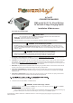
PM3-24V Series Manual

Second, attach a multimeter instrument between the positive and negative terminals of the Converter/Charger. Then energize
Copyright© 2012, Fieldstone Products Inc. Fieldstone Products Inc. reserves the right to make changes in the product at any time,
without notification. Install Guide PMxx-24-3 19 October 2015
POS
POS
–
9.
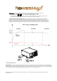
TEST. First, disconnect all loads and battery on the Converter/Charger by removing all 24 VDC connections
from + or .
the 120 VAC Converter/Charger circuit. Test for proper output power using the multimeter. Measure the output voltage from
the
positive and negative terminals. The voltage should read
27.6 +/- 0.1 VDC. Add 24 VDC load connections to draw about
12
Amps from the Converter/Charger. Recheck the voltage, which should remain approximately the same as at no load.
10.BATTERY. With the 120 VAC disconnected, reconnect the + or
positive terminal to a known good battery. With the
converter 120 VAC energized, measure the voltage at the converter and at the battery. The voltage should be about the same in
both locations. As with any battery it is important that the fluid level be checked on a regular basis. When continuously connected
to any charging source all batteries will “Gas” and lose some fluid.
NOTE: Before
removing and replacing the Converter/charger, perform the following checks:
a. Disconnect the AC power from the vehicle/device.
b. Disconnect the wiring and Battery from the Converter Positive
c. Re-connect the AC power to energize the Converter.
output terminal.
d. Using a voltmeter, measure the voltage at the Converter and Output terminals.
> The Converter/Charger is OK if the voltage reading is between 27 VDC and 28 VDC (typically 27.6 VDC).
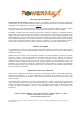
> Otherwise check the table below:
ESUAC ELBISSOP NOITIDNOC
No 24 VDC output
120 VAC not connected to coach or the coach AC circuit breaker is in the off position.
Reversed battery fuses blown. (Battery wiring connections are reversed),
Severe overload or shorted load. Remove all loads and retest per above instructions.
Converter/Charger internal failure.
Converter cycles On & Off
Fan air flow is inadequate or blocked. (1” minimum free air space at each end required)
Converter/Charger internal failure.
Reversed Battery fuses blown
Battery wiring connections are reversed.
Defective battery, possible bad cells.
24 VDC output is too low
Attached load exceeds rating of the Converter/Charger.
Defective battery, possible bad cells.
Converter/Charger internal failure.
+
+
TROUBLESHOOTING
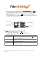
‘Reversed-Battery’ Fuses
Chassis B
LED
onding Lug
24 VDC Output Terminals
AIR FLOW FAN
(on back-side)
.
.
.
.
Blows air out of
front grill vents.