
Operation Manual


POWP4010 EN
Copyright © 2018 VARO P a g e | 5 www.varo.com
6 SPECIFIC SAFETY WARNINGS FOR CIRCULAR SAWS
▪ Make sure that all devices screening the saw blade are in perfect working order.
▪ Make sure that the saw blade is screened correctly. Especially observe the following
instructions:
Never block the saw blade guard. Repair a jammed saw blade guard before using the
machine again.
Replace a broken tension spring before using the machine again.
Never remove the riving knife. The distance between the toothed rim and the riving knife
should be 5 mm maximum. The height difference between the riving knife and the
toothed rim should be 5 mm maximum.
▪ Do not use saw blades made of HSS steel.
▪ Do not use bent, deformed or otherwise damaged saw blades.
▪ Do not use saw blades which do not meet the specifications stated in this manual.
▪ Before sawing, remove all nails and other metal objects from the workpiece.
▪ Never start sawing before the saw reaches its full speed.
▪ Securely clamp the workpiece. Never attempt to saw extremely small workpieces.
▪ Only put the machine aside after switching off and when the saw blade has come to a
complete standstill.
▪ Never try to slow the saw blade down by exerting pressure on the side.
▪ Before performing maintenance to the machine, always unplug the machine.
7 ASSEMBLY
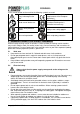
7.1 Replacing the saw blade (Fig. 1)
Only use sharp and undamaged saw blades. Cracked or bent saw blades must be replaced
immediately.
▪ Place this circular saw on its side on a flat surface. Advice you bring the base plate (1)
down as if a minimum depth cut which is ease to operate change the blade.
▪ Push the spindle lock button (15) toward motor housing as the arrow shows in Fig. 1 and
firmly hold it.
▪ Turn the blade clamp bolt (13) anti-clockwise by using the hex key (21) that supplied with
the tool.
▪ Remove the blade clamp bolt (13) and outer flange (14).
▪ Raise the lower guard (2) by using the lever for lower guard (7), and then remove the saw
blade.
▪ Clean the saw blade flanges, then mount the new saw blade onto the output spindle and
against the inner flange.
▪ Make sure the saw teeth and arrow on the blade is to be the same direction as the arrow
on the lower guard.
▪ Reinstall the outer flange, and tighten the blade clamp bolt.
▪ Make sure that the saw blade runs freely by turning the blade by hand.
Before replacing the saw blade always unplug the tool.
7.2 Depth adjustment (Fig. 2)
▪ Loosen the adjusting screw lock lever for depth adjustment (20).
▪ Hold the base plate (1) flat against the edge of the work piece and lift the body of the saw
until the blade is at the right depth determined by the depth gauge (22) of cut scale (align
the scale line).
▪ Tighten the adjusting screw the lock lever for depth adjustment.