
Technical data


POWX093 EN
Copyright © 2015 VARO P a g e | 8 www.varo.com
7.5 Inserting and removing the chuck and cutting heads n
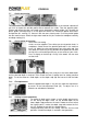
The cutting machine is supplied with a set of 12 mm cutting
heads. There are a number of heads for cutting various
profiles in wood. One example is a decorative edge on a
skirting board. The machine is supplied with two chucks for 8
mm and 12 mm. Numerous cutting heads are available for
different profiles.
Some heads are too large and leave no space for the dust-
extraction system. In this casep a mask should be worn.
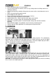
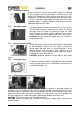
CAUTION: Ensure that the machine is not connected to the
power supply. To insert the chuck, locate the spindle lock at
the front of the machine. Press it down and hold it in this
position. Using the wrench provided, loosen the chuck nut by
turning in an anticlockwise direction (10). Remove the chuck
and clean the spindle (11). Insert the other chuck in the
spindle and screw on the nut finger tight. To insert a cutter
head, loosen the chuck nut and insert the shaft of the cutter
head (12). Ensure thai at least 20 mm or halt the length of the
cutter-head shaft is inserted into the chuck. If insertion depth is
less, the cutter head will be instable and may work loose.
Press the spindle lock, hold it in position, and tighten the chuck
nut. Repeatedly check the tightness of the nut during your
work.
CAUTION: Handle the cutter heads carefully. They are sharp
and may cause cuts.
CAUTION: Before switching the machine on, ensure that the
chuck nuts are tight.
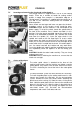
7.6 Cutter guide sleeve
The cutter guide sleeve is attached to the base of the
machine and ensures that the machine can follow a certain
cutting profile. Only certain sizes of cutter head can be used.
The si2e is limited by the size of the hole in the cutter guide
sleeve.
The dust-extraction system can be used with this accessory.
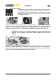
To install the guide plate, lay the cutting machine on its side.
Loosen and remove the two bolts for the dust-extraction
system. Remove the four cross-head screws attaching the
plastic base to the casting (13). Note the recess in the plastic
base. Hold the guide plate with the sleeve to the outside and
place it in the recess (14). Align the holes in the plastic base
with the threaded holes in the casting and tighten the four
cross-head screws (15). Re-install the dust-extraction
components and secure it with bolts and nuts.