
User Manual

POWXG3005 EN
Copyright © 2014 VARO P a g e | 6 www.varo.com
7 ASSEMBLY
The trimmer is supplied with some components which need to be assembled. Please
proceed as follows:
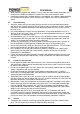
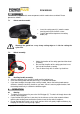
7.1 Safety guard assembly
Insert the safety guard (11) onto the motor
housing and secure it with 4 screws.
Carfully peel off the tape overt he cutting
blade (14)
Warning: the guard has a very sharp cutting edge on 1 side for cutting the
nylon line.
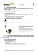
7.2 Wheel assembly
Adjust the location of the safety guard and the wheel
assembly.
Be sure that the pillar of the safety guard can insert
the hole of the wheel assembly.
Then fix them firmly with 2 screws by the driver.
7.3 Auxiliary handle assembly
Adjust the location of the auxiliary handle and the locking base.
Insert the locking knob and lock them firmly in a clockwise direction.
If you want to adjust the angle of the auxiliary handle, loosen the locking knob counter
clockwise, rotate the auxiliary handle as you want. When it reach a proper location, lock
the locking knob firmly in a clockwise direction again.
8 OPERATION
8.1 Starting
To switch on the trimmer first press the On/Off trigger (5). To switch off simply release the
On/Off switch trigger(5)
If you find that the nylon line is too short, let the trimmer run for a few seconds without
touching the working area to allow the trimmer to cut the line after it lengthens.
Do not overload the trimmer, cut in small sections which will greatly improve efficiency by
keeping the trimmer running at high speed,