
User Manual

NEW INSTALLATION
Note:
Requires 1
3
⁄8″ diameter opening
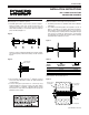
1. Assemble push button components as shown in figure 1.
During assembly, make sure electrical switch “B” sits
squarely in housing “A.” Take care not to pinch electrical
wires while assembling. Lock electrical switch securely into
place with threaded pipe “C.”
Figure 1
All pieces must be adequately tightened to prevent vandal-
ism and tampering. Finished assembly should resemble
figure 2.
Figure 2
2. Place finished assembly through 1
3
⁄8″ diameter opening
and secure firmly with brass locknut “D” against backside
of wall or fixture.
3. Connect wiring (from push button to control box) using
modular telephone connector. Powers’ new push button
switch assembly is completely compatible with all current
ESP electronic components, including both the group and
individual control centers.
RETROFIT FOR EXISTING INSTALLATION
Note:
Used when hole through wall is greater than 2″
1. Assemble push button as detailed under New Installation
instructions.
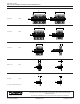
2. Two additional mounting plates are required as shown in
figure 3. See table 3.1 for proper sizing and kit numbers.
Place stainless (round) mounting plate “A” over push but-
ton assembly. Place assembly with mounting plate through
wall. Secure assembly by placing brass (rectangular)
mounting plate “B” on back side of wall (covering opening)
and tighten down with brass lock nut.
Figure 3
Table 3.1
Final installation will resemble Figure 4.
Figure 4
(Continued on reverse)
Exposed stainless
mounting plate
Existing wall
Locknut
Concealed brass
mounting plate
Thru Hole
Diameter
Exposed Stainless
Mounting Plate
Concealed Brass
Mounting Plate
> 2″ ≤ 3″
> 3″ ≤ 4″
> 4″ ≤ 5″
> 5″ ≤ 6″
444-304A
444-304B
444-304C
444-304D
444-285A
444-285B
444-285C
444-285D
Mounting plate,
wall, or fixture
A B C D
INSTALLATION INSTRUCTIONS
ESP
™
PIEZO PUSH BUTTON
CONCEALED SHOWERS
Form ESP-PBII