
Install Instructions

Installation n
1. Locate suitable place for the tempering valve. Valves should
be accessible for service and adjustment, and be as close to
the point of use as possible.
2. Bleed pressure from the system.
3. Route copper tubing or piping to fit valve dimensions.
4. For valves with Quick-Connect tailpieces refer to “Quick-
Connect Installation” instructions below.
5. Remove tailpieces from the valve and make sure union nuts
are over the tubing/piping before connecting to the tailpiece.
If soldering, remove unions and gaskets from valve body prior to
soldering to prevent damage to valve from excessive heat.
6. Flush piping again, install valve using filter gasket on
hot and cold water inlets and fiber gasket on mixed
water outlet.
7. Turn on the cold and hot water. If any leaks are observed,
tighten connections as necessary to stop leak
before proceeding.
HydroGuard
®
Thermostatic Tempering Valves
LFLM495
IS-P-LM495
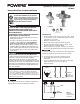
Figure 1.
Typical
ASSE 1069
Application
Cold
Hot
LFLM495
Mixed
LFLM495-1
LFLM495-5
COLD WATE
R
SUPPLY
POWERS SERIES LM495 OR
LFLM495 WITH INTEGRAL
CHECKS AND SCREENS
HOT WATER SUPPLY
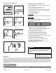
Figure 2.
Single/Two
Handle Faucet
Application
Advanced
Thermal Activation
WARNING
!
Read this Manual BEFORE using this equipment.
Failure to read and follow all safety and use infor-
mation can result in death, serious personal injury,
property damage, or damage to the equipment.
Keep this Manual for future reference.
FAILURE TO COMPLY WITH PROPER INSTALLATION
AND MAINTENANCE INSTRUCTIONS COULD
CONTRIBUTE TO THE VALVE FAILURE, RESULTING IN
INJURY AND/OR DEATH.
TO ENSURE THE ACCURATE AND RELIABLE OPERATION
OF THIS PRODUCT, IT IS ESSENTIAL TO:
• Properly design the system to minimize pressure and
temperature variations.
• This valve is not factory preset and can be adjusted
to deliver scalding temperatures. Check outlet tem-
perature to ensure it does not exceed 105°F (41°C).
Make sure temperature limit stop is properly re-set to
maximum 105°F (41°C) following valve maintenance or
repair. Tampering with limit stop in any way may result
in scalding temperature causing serious bodily harm
and/or death.
WARNING
!
WARNING
!
Need for Periodic Inspection and Yearly Maintenance:
Periodic inspection and yearly maintenance by a licensed
contractor is required. Corrosive water conditions
and/or unauthorized adjustments or repair could render
the valve ineffective for service intended. Regular checking
and cleaning of the valve’s internal components and check
stops helps assure maximum life and proper product func-
tion. Frequency of cleaning and inspection depends upon
local water conditions.
You are required to consult the local building and plumbing
codes prior to installation. If the information in this manual is
not consistent with local building or plumbing codes, the local
codes should be followed. Inquire with governing authorities for
additional local requirements.
WARNING
!
WARNING
!
NOTICE
Flush all pipes thoroughly before installation. Installation and
field adjustment are the responsibility of the installer.
Installation Instructions