TWO STAGE GAS SNOW THROWER MODEL DB7659-22 Questions, problems, missing parts? If you have questions or need technical support, call the Amerisun customer service department at 1-800-791-9458 or visit Amerisuninc.com or e-mail support@amerisuninc.com. For engine related problems, questions and warranty service call the engine manufacturer 1-877-274-2214. WARNING! Read and follow all safety rules and instructions in this manual before attempting to operate this machine.
TABLE OF CONTENTS Safety....................................................................................................................................................... 2 Feature Identification ................................................................................................................................ 5 Box Contents ............................................................................................................................................ 6 Assembly ...............
SAFETY This symbol points out important safety instructions which, if not followed, could endanger the personal safety and or property of yourself and others. Read and follow all instructions in this manual before attempting to operate this machine. Failure to comply with these instructions may result in personal injury. WARNING! This machine was built to be operated according to the safe operation practices in this manual.
Service • The auger impeller control lever is a safety device. Never bypass its operation. Doing so makes the machine unsafe and may cause personal injury. • The control levers must operate easily in both directions and automatically return to the disengaged position when released. • Never operate with a missing or damaged chute assembly. Keep all safety devices in place and working. • Never run an engine indoors or in a poorly ventilated area.
• When staring engine, pull cord slowly until resistance is felt, then pull rapidly, Rapid retraction of starter cord (kickback) will pull hand and arm toward engine faster then you can let go. Broken bones, fractures, bruises or sprains could result. • If situations occur which are not covered in this manual, use care and good judgment contact customer support for assistance.
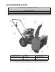
FEATURE IDENTIFICATION TECHNICAL SPECIFICATIONS Clearing Width: DB7659 22 Clearing Height: 16 inches 4 Forward and 2 Reverse Speeds Engine Displacement: 208 cc, 4 stroke A - Drive Control Handle B - Speed Control Lever C - Auger Control Handle D - Chute Rotation Handle E - Engine F - Skid Shoe G - Augers H - I mpe l l er I - Snow/Ice Clean Out Tool J - Chute Assembly - For a complete parts breakdown go to www.amerisuninc.
A. Drive Control Handle Shave Plate (not shown) The Drive Control is used to engage and disengage the drive wheels. Pull up on the Drive Control handle to engage the wheels; release to disengage. B. Speed Control Lever The Shave Plate maintains contact with pavement as the snow thrower is propelled, allowing snow close to pavement's surface to be discharged. BOX CONTENTS The Speed Control Lever is located in the right side and is used to set the drive speed and direction of travel.
2. Attached the upper handle to the lower handle using (4) nut,washers and bolts. 2. Hold the discharge chute and handle to align the mounting holes to chute base mount holes. Insert the screws and washers and secure with locknuts. Do not over-tighten the screws. NOTICE: Do not bend or kink the control cables. The cables should be routed under the handle assembly and not wrapped around the handle or knobs. The cables must move freely and not bind. 3.
OPERATION Skid Shoe Installation and Adjustment PLEASE REFER TO ENGINE MANUAL (SEPARATE DOCUMENT) FOR ENGINE OPERATION INSTRUCTIONS. 1. Locate the pair of skid shoes from parts bag and remove the bolts. 2. Loosely install the skid shoes using the bolts, washers and hex nuts as shown on each side of the auger housing. The following section describes steps to prepare your Snow Thrower for use.
WARNING! DO NOT USE YOUR HANDS TO UNCLOG CHUTE. Stop the motor before removing debris. Use the supplied clean out tool to unclog the chute. Do not walk in front of your running Snow Thrower. Do not direct discharged snow towards bystanders. • Do not apply additional weight to be top of the engine since this may damage the engine. • Some parts of your Snow Thrower may freeze under extreme temperature conditions. Do not attempt to operate your Snow Thrower with frozen parts.
Chute Discharge Angle Adjustment WARNING! Always disengage the drive and auger control handles before making adjustments. Make sure the augers are stopped and the machine is not moving. The angle of the chute deflector controls the discharge distance of the snow. Raising the angle will increase the distance. Lowering the angle will decrease the distance. Note: There is no neutral drive setting since the drive control handle must be engaged for movement.
Clearing Snow Stopping Start the engine (see ENGINE manual) once your Snow Thrower has been running outside for several minutes, it is now ready for use. Make sure the path in front of your Snow Thrower is free from people, animals, objects, and all other obstructions except for snow. When finished using your Snow Thrower, perform the following steps to shut it down. 1. Engage the auger and impeller for 30 seconds to clear any remaining snow inside your Snow Thrower. 2.
Check the bolts at frequent intervals for proper tightness to ensure that the equipment is in safe working condition. WARNING! DO NOT OVER-INFLATE THE TIRES. Over-inflating could cause a tire to burst and cause severe bodily injury. After each snow removal session, run the Snow Thrower for a few minutes to prevent the collector/impeller from freezing. Stop the engine, wait for all revolving parts to stop completely, and wipe residual ice and snow off the unit.
Checking auger gear box oil level Service yearly-check the auger gear box oil and add oil if necessary 1. Clean area around pipe plug. 2. Remove pipe plug from top of gear box. 3. Check oil level. The oil should be to a point of over flowing at the opening. 4. Add GL-5 or GL-6, SAE 85-95EP gear oil lubricant to the point of overflowing. NOTE: Do not use synthetic oil. 5. Install the pipe plug in the gear box. 6. Every 3 Years, replace lubricant. Drain plug is on the bottom of the housing.
4. Adjustment is made by changing the position of the lower cable in the adjustment plate holes (1 to 9). Only move the lower cable diagonally one hole at a time from its original position. To adjust the cables one cable should be loosened and the other tightened equally until there is a positive direction change when the lever is shifted between F1 and R1. The middle position between these two settings is neutral (there is no actual neutral "notched" position on the control panel).
Note: During operation the augers turn at a slower speed than the impeller, this is normal. The augers are used to chop and cut the snow and direct it into the impeller which is rotating at a high speed to throw the snow up and out of the chute. Over time, the auger cable tension may loosen and or the auger belt may stretch. The auger cable will require periodic adjustment to compensate for these changes.
(1 to 9). Only move the lower cable diagonally one hole at a time from its original position. Note: The upper cable end must be in the upper single center hole of the adjustment plate. Do not change the position of the upper cable. 5. Connect the upper cable to the control handle. 6. Start the engine and engage the auger to test the operation of the auger. Note: With the auger control handle at the full released position, the cable should be barely tight.
6. Remove the belt from the drive pulley while pulling the right side of the auger housing away from the main frame just enough to access the belt and auger pulley. 1 – Auger Brake 8. Remove the auger belt. Auger Belt Installation WARNING! Entanglement Hazard - Before performing any service procedures, make sure the engine is off and remove the spark plug wire from the spark plug to ensure the engine cannot accidently start.
WARNING! Ensure the belt cover is installed and all safety guards are in place before the engine is started and at all times when the engine or machine are operating. pulley while pulling the auger housing into position with the main frame. 8. Install belt cover using 2 hex head screws. Make sure the auger cable is routed outside the belt cover as shown. 4. Install and/or tighten the hex screws attaching the auger housing to the main frame. Tighten all fasteners securely, do not over tighten. 5.
• • • • • • Storage Missing pieces Cracks and tears Burning Uneven wear patterns General damage Foreign material on belt, oil, grease, dirt etc. WARNING! Never store your Snow Thrower for extended periods of time with fuel in the tank. Fuel stabilizer can be added to the fuel to extend its shelf life for storage. Store the unit, in a locked, dry place out of the reach of children to prevent unauthorized use or damage. Cover loosely with a tarp for added protection.
TROUBLESHOOTING Problem Possible Causes Remedy WARNING-Before attempting to make any inspections, repairs or adjustments, stop the engine, wait for all moving parts to stop moving and carefully disconnect the engine spark plug wire. If tipping or turning the snow blower is required for any inspection or repair, first wait until the engine is cool to the touch and then drain the engine of all fuel and oil into suitable containers and store or dispose of in a proper manner.
1 Engine Overheats Remove air flow restrictions from engine 2 Low oil level 2 1 CHOKE in ON or partial ON position 1 Move CHOKE lever to RUN 2 Water in fuel 2 3 Fuel incorrect, old or stale 3 6 Blocked or clogged fuel 4 system or line Carburetor is in need of 5 cleaning Spark plug wire loose 6 7 Faulty spark plug 7 8 Gas cap vent hole plugged 8 9 Engine oil over filled 9 5 Engine smokes excessively 1 Check oil level on dipstick.
Drive System 1 Drive control cable loose, broken or binding 2 Drive belt loose or damaged Friction drive wheel is worn or 3 damaged No forward or reverse drive Friction drive wheel wet or 4 movement when slipping drive handle engaged 5 Wheel locked, won't move 6 Drive speed control stuck in gear or won't change gears Wheel to axle pins broken or missing Speed control lever loose or 1 damaged, not moving speed control cables.
Impeller not connected to 9 impeller shaft, impeller or shaft damaged or roll pins broken 9 Replace roll pins or impeller as necessary 10 Inadequate amount of snow Ingest an adequate amount of snow to 10 allow snow to compact enough to be moved through augers and into impeller.
TWO YEAR WARRANTY Amerisun Inc. and LCT Engine Corporation jointly warrant this product for two years against defects in material or workmanship when used for normal residential purposes. The manufacturer will, at its option, repair or replace, for the original purchaser, any part or parts which have been found to be defective in material and workmanship. Residential use means use of the product on the same lot as your home.