TWO STAGE GAS SNOW THROWER MODEL DB7659-22 and 24 Questions, problems, missing parts? If you have questions or need technical support, call the Amerisun customer service department at 1-800-791-9458 or visit Amerisuninc.com and e-mail support@amerisuninc.com. For engine related problems, questions and warranty service call the engine manufacturer 1-877-274-2214. WARNING! Read and follow all safety rules and instructions in this manual before attempting to operate this machine.
TABLE OF CONTENTS Safety....................................................................................................................................................... 2 Feature Identification ................................................................................................................................ 6 Box Contents ............................................................................................................................................ 7 Assembly ...............
SAFETY This symbol points out important safety instructions which, if not followed, could endanger the personal safety and or property of yourself and others. Read and follow all instructions in this manual before attempting to operate this machine. Failure to comply with these instructions may result in personal injury. WARNING! This machine was built to be operated according to the safe operation practices in this manual.
• Exercise caution to avoid slipping or falling, especially when operating in reverse. • Stay alert, watch what you are doing and use common sense when operating your Snow Thrower. • Do not use your Snow Thrower while you are tired or under the influence of drugs, alcohol, medication. A moment of inattention while operating the Snow Thrower may result in severe bodily injury. • NEVER LEAVE YOUR RUNNING SNOW THROWER UNATTENDED. Stop the engine.
• If the machine should start to vibrate abnormally, stop the engine, disconnect the spark plug wire and ground it against the engine.Inspect thoroughly for damage. Repair any damage before starting and operating. • Disengage all control levers and stop engine before you leave the operating (behind the handles). • Wait until the auger /impeller comes to a complete stop before unclogging the chute assembly, making any adjustments, or inspections. • Never put your hand in the discharge or collector openings.
Safety Symbols This page depicts and describes safety symbols that may appear on this product. Read, understand and follow all instructions on the machine before attempting to assemble and operate.
FEATURE IDENTIFICATION TECHNICAL SPECIFICATIONS Clearing Width: DB7659 22 and 24 inches Clearing Height: 16 inches 4 Forward and 2 Reverse Speeds Engine Displacement: 208 cc, 4 stroke A - Drive Control Handle B - Speed Control Lever C - Auger Control Handle D - Chute Rotation Handle E - Engine F - Skid Shoe G - Augers H - Impeller I - Snow/Ice Clean Out Tool J - Chute Assembly - 6
A. Drive Control Handle Shave Plate (not shown) The Drive Control is used to engage and disengage the drive wheels. Pull up on the Drive Control handle to engage the wheels; release to disengage. B. Speed Control Lever The Shave Plate maintains contact with pavement as the snow thrower is propelled, allowing snow close to pavement's surface to be discharged. The Speed Control Lever is located in the right side and is used to set the drive speed and direction of travel.
secure with locknuts. Do not over-tighten the screws. NOTICE: Do not bend or kink the control cables. The cables should be routed under the handle assembly and not wrapped around the handle or knobs. The cables must move freely and not bind. 3. Secure the speed control cables to the handle with provided clips. Note: Do not secure the auger or drive control cables with the clips. NOTICE: Make sure all fasteners are tightened before starting the machine. Handle Assembly 1.
4. Place a spacer board on the ground underneath the auger shave plate between the skid shoes. The thickness of the board should be the same as the height above the ground you wish to raise the auger shave plate. The skid shoes should not touch the board. 5. With the two (2) nuts loose allow the skid shoe to slide to the ground then tighten the nuts to secure the skid shoe. OPERATION Skid Shoe Installation and Adjustment 1. Locate the pair of skid shoes from parts bag and remove the bolts. 2.
WARNING! DO NOT USE YOUR HANDS TO UNCLOG CHUTE. Stop the motor before removing debris. Use the supplied clean out tool to unclog the chute. Do not walk in front of your running Snow Thrower. Do not direct discharged snow towards bystanders. • Do not apply additional man-made load to the engine since this may damage the engine. • Some parts of your Snow Thrower may freeze under extreme temperature conditions. Do not attempt to operate your Snow Thrower with frozen parts.
Chute Discharge Angle Adjustment WARNING! Always disengage the drive and auger control handles before making adjustments. Make sure the augers are stopped and the machine is not moving. The angle of the chute deflector controls the discharge distance of the snow. Raising the angle will increase the distance. Lowering the angle will decrease the distance. Note: There is no neutral drive setting since the drive control handle must be engaged for movement.
Clearing Snow Stopping Start the engine (see ENGINE manual) once your Snow Thrower has been running outside for several minutes, it is now ready for use. Make sure the path in front of your Snow Thrower is free from people, animals, objects, and all other obstructions except for snow. When finished using your Snow Thrower, perform the following steps to shut it down. 1. Engage the auger and impeller for 30 seconds to clear any remaining snow inside your Snow Thrower. 2.
After each snow removal session, run the Snow Thrower for a few minutes to prevent the collector/impeller from freezing. Stop the engine, wait for all revolving parts to stop completely, and wipe residual ice and snow off the unit. Rotate the chute rotation handle several times to remove any excess snow.
3. Slide up the slip cover to access the adjustment plate. 1. Turn off the engine and wait for all moving parts to come to a complete stop. Remove any remnants of the broken shear pin. It may be necessary to unscrew the nut from the broken shear pin and drive out the broken pin. 2. Insert a new shear pin through the hole in the auger shaft and tighten using the shear pin hex nut. Do not over-tighten the hex nut. NOTICE: Never replace the shear pins with standard pins or fasteners.
Note: The upper cable end must be in the upper single center hole of the adjustment plate. Do not change the position of the upper cable. 5. Connect the upper cable to the control handle. 6. Start the engine and engage the drive control handle to test the operation of the drive engagement. Note: With the drive control handle at the full released position, the cable should be barely tight. Some slack in the cable may be required to ensure the drive control is not engaging the drive friction wheel.
Note: During operation the augers turn at a slower speed than the impeller, this is normal. The augers are used to chop and cut the snow and direct it into the impeller which is rotating at a high speed to throw the snow up and out of the chute. Over time, the auger cable tension may loosen and or the auger belt may stretch. The auger cable will require periodic adjustment to compensate for these changes.
(1 to 9). Only move the lower cable diagonally one hole at a time from its original position. Note: The upper cable end must be in the upper single center hole of the adjustment plate. Do not change the position of the upper cable. 5. Connect the upper cable to the control handle. 6. Start the engine and engage the auger to test the operation of the auger. Note: With the auger control handle at the full released position, the cable should be barely tight.
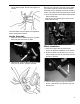
6. Remove the belt from the drive pulley while pulling the right side of the auger housing away from the main frame just enough to access the belt and auger pulley. 1 – Auger Brake 8. Remove the auger belt. Auger Belt Installation WARNING! Entanglement Hazard - Before performing any service procedures, make sure the engine is off and remove the spark plug wire from the spark plug to ensure the engine cannot accidently start.
pulley while pulling the auger housing into position with the main frame. WARNING! Ensure the belt cover is installed and all safety guards are in place before the engine is started and at all times when the engine or machine are operating. 8. Install belt cover using 2 hex head screws.Make sure the auger cable is routed outside the belt cover as shown. 4. Install and/or tighten the hex screws attaching the auger housing to the main frame. Tighten all fasteners securely, do not over tighten. 5.
• • • • • • Missing pieces Cracks and tears Burning Uneven wear patterns General damage Foreign material on belt, oil, grease, dirt etc. Inspect the auger pulleys: • Broken sheave or hub • Loose or missing mounting bolts • Bent or "out-of-round" condition (pulley not spin true on shaft) • Misaligned pulleys Storage WARNING! Never store your Snow Thrower for extended periods of time with fuel in the tank. Fuel stabilizer can be added to the fuel to extend its shelf life for storage.
TROUBLESHOOTING Problem Possible Causes Remedy WARNING - Before attempting to make any inspections, repairs or adjustments, stop the engine, wait for all moving parts to stop moving and carefully disconnect the engine spark plug wire. If tipping or turning the snow blower is required for any inspection or repair, first wait until the engine is cool to the touch and then drain the engine of all fuel and oil into suitable containers and store or dispose of in a proper manner.
Drive System No forward or reverse drive movement when drive handle engaged Drive speed control stuck in gear or wont change gears Drive speed control allows only one direction forward or reverse Drive engaged when drive control handle released 1 Drive control cable loose, broken or binding 1 Repair or adjust drive control cable and adjust tension, see Auger and Drive Cable Adjustment 2 Drive belt loose or damaged 2 Check drive belt tension pulley for damage or incorrect tension, repair as necessary.
WARRANTY TWO YEAR WARRANTY ENGINE WARRANTY See the ENGINE manual included with this snow thrower for engine warranty information. For all engine related warranty issues contact LCT engine corporation - phone 1-877-274-2214. WARRANTY For two years from date of retail purchase within U.S.A., the manufacturer will, at its option, repair or replace, for the original purchaser, free of charge, any part or parts found to be defective in material or workmanship.