TWO STAGE GAS SNOW THROWER MODEL DB7103-24 and 26 Questions, problems, missing parts? If you have questions or need technical support, call the Amerisun customer service department at 1-800-791-9458 or visit Amerisuninc.com or e-mail support@amerisuninc.com. For engine related problems, questions and warranty service call the engine manufacturer 1-877-274-2214. WARNING! Read and follow all safety rules and instructions in this manual before attempting to operate this machine.
TABLE OF CONTENTS Safety....................................................................................................................................................... 2 Feature Identification ................................................................................................................................ 5 Box Contents ............................................................................................................................................ 6 Assembly ...............
SAFETY This symbol points out important safety instructions which, if not followed, could endanger the personal safety and or property of yourself and others. Read and follow all instructions in this manual before attempting to operate this machine. Failure to comply with these instructions may result in personal injury. WARNING! This machine was built to be operated according to the safe operation practices in this manual.
Service The auger impeller control lever is a safety device. Never bypass its operation. Doing so makes the machine unsafe and may cause personal injury. The control levers must operate easily in both directions and automatically return to the disengaged position when released. Never operate with a missing or damaged chute assembly. Keep all safety devices in place and working. Never run an engine indoors or in a poorly ventilated area.
When staring engine, pull cord slowly until resistance is felt, then pull rapidly, Rapid retraction of starter cord (kickback) will pull hand and arm toward engine faster then you can let go. Broken bones, fractures, bruises or sprains could result. If situations occur which are not covered in this manual, use care and good judgment contact customer support for assistance.
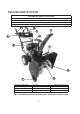
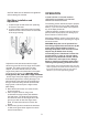
FEATURE IDENTIFICATION TECHNICAL SPECIFICATIONS Clearing Width: DB7103 24 and 26 inches Clearing Height: 21 inches 6 Forward and 2 Reverse Speeds Engine Displacement: 208cc, 4 stroke A K B J C L D E I H G F A - Drive Control Handle B - Speed Control Lever C - Auger Control Handle D - Chute Rotation Handle E - Engine F - Skid Shoe G- Augers H - I mpe l l er I - Snow/Ice Clean Out Tool J - Chute Assembly K - Chute Deflector Lever L - Light For a complete parts breakdown go to www.amerisuninc.
A. Drive Control Handle K. Chute Deflector Lever Located on the right side of the upper handle, the Drive Control is used to engage and disengage the drive wheels. Squeeze the Drive Control handle against the upper handle to engage the wheels; release to disengage. B. Speed Control Lever The angle of the chute deflector controls the discharge distance of the snow. Raising the angle will increase the distance . Lowering the angle will decrease the distance.
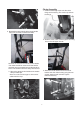
Chute Assembly 1. Install the discharge chute onto the chute flange on the housing. The chute only rests on the flange. 2. Attached the upper handle to the lower handle using four (4) knobs, washers and bolts. 2. Slide the chute crank rod through the mounting hole on the left upper handle. NOTICE: Do not bend or kink the control cables. The cables should be routed under the handle assembly and not wrapped around the handle or knobs. The cables must move freely and not bind. 3.
OPERATION NOTICE: Make sure all fasteners are tightened before starting the machine. PLEASE REFER TO ENGINE MANUAL (SEPARATE DOCUMENT) FOR ENGINE OPERATION INSTRUCTIONS. Skid Shoe Installation and Adjustment The following section describes steps to prepare your Snow Thrower for use. If after reading this section, if you are unsure about how to perform any of the steps please call 1-800-791-9458 for customer service.
Start your clearing path by throwing snow in a back and forth motion. To clear in the opposite direction, stop your Snow Thrower and pivot it on its wheels to face the opposite direction. Make sure to overlap clearing paths. Determine the direction of the wind. If possible, move in the same direction as the wind so that the snow is not thrown against the wind, back into your face and on the just cleared path.
Drive Speed Control Lever Chute Discharge Angle Adjustment Move the drive speed control lever to the desired speed. There are eight(8) settings:six (6) forward speeds and two (2) reverse speeds. 1 is the slowest forward speed and 6 is the fastest forward speed. R1 is the slowest reverse speed and R2 is the fastest reverse speed. WARNING! Always disengage the drive and auger control handles before making adjustments. Make sure the augers are stopped and the machine is not moving.
OPERATING YOUR SNOW THROWER move or throw. Wet snow will tend to clog and stick more to the augers and chute. Keep the auger engaged as much as possible when clearing wet snow to help prevent clogging. Starting Please refer to ENGINE manual (separate document) for engine operation instructions. WARNING! If snow is filled with foreign material, damage to the snow thrower may result. Avoid snow with foreign materials.
Check the bolts at frequent intervals for proper tightness to ensure that the equipment is in safe working condition. WARNING! DO NOT OVER-INFLATE THE TIRES. Over-inflating could cause a tire to burst and cause severe bodily injury. After each snow removal session, run the Snow Thrower for a few minutes to prevent the collector/impeller from freezing. Stop the engine, wait for all revolving parts to stop completely, and wipe residual ice and snow off the unit.
Checking auger gear box oil level Service yearly-check the auger gear box oil and add oil if necessary 1. Clean area around pipe plug 2. Remove pipe plug from top of gear box 3. Check oil level. The oil should be to a point of over flowing at the opening 4. Add GL-5 or GL-6, SAE 85-95EP gear oil lubricant to the point of overflowing NOTE: Do not use synthetic oil 5. Install the pipe plug in the gear box. 6. Every 3 Years, replace lubricant. Drain plug is on the bottom of the housing.
4. Adjustment is made by changing the position of the lower cable in the adjustment plate holes (1 to 9). Only move the lower cable diagonally one hole at a time from its original position. Note: The upper cable end must be in the upper single center hole of the adjustment plate. Do not change the position of the upper cable. 5. Connect the upper cable to the control handle. 6. Start the engine and engage the drive control handle to test the operation of the drive engagement.
Auger Belt Tension Adjustment WARNING! Entanglement Hazard - Before performing any adjustment procedures, make sure the engine is off and remove the spark plug wire from the spark plug to ensure the engine cannot accidently start. Never adjust belt tension with the engine running. The auger cable is located on the left side (when standing behind the snow blower) and is made up of an upper and lower cable connected by an adjustment plate.
4. Adjustment is made by changing the position of the lower cable in the adjustment plate holes (1 to 9). Only move the lower cable diagonally one hole at a time from its original position. 2. Remove 2 hex head screws and remove belt cover. Note: The upper cable end must be in the upper single center hole of the adjustment plate. Do not change the position of the upper cable. 5. Connect the upper cable to the control handle. 6. Start the engine and engage the auger to test the operation of the auger.
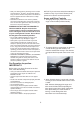
5. Right Side - Remove the hex nuts, lock washers and flat washers attaching the auger housing to the main frame. 7. Push the auger tension pulley arm to move the auger brake, away from the belt to allow removal of the belt. 6. Remove the belt from the drive pulley while pulling the right side of the auger housing away from the main frame just enough to access the belt and auger pulley. 8. Remove the auger belt.
2. Push the auger tension pulley arm to move the auger brake to allow access for installation of the belt into the auger pulley. 1 – Auger Brake 3. Route the belt to the inside of the tension pulley and install the auger belt onto the drive pulley while pulling the auger housing into position with the main frame. Note: The belt guide pin helps keep the belt in the pulley when the belt is disengaged. The pin should not be tight to the belt.
When replacing your snow blower auger belt it is important to determine the cause of the failure (if applicable) and take corrective action to avoid repeated failure.
TROUBLESHOOTING Problem Possible Causes Remedy WARNING-Before attempting to make any inspections, repairs or adjustments, stop the engine, wait for all moving parts to stop moving and carefully disconnect the engine spark plug wire. If tipping or turning the snow blower is required for any inspection or repair, first wait until the engine is cool to the touch and then drain the engine of all fuel and oil into suitable containers and store or dispose of in a proper manner.
1 Engine Overheats Remove air flow restrictions from engine 2 Low oil level 2 1 CHOKE in ON or partial ON position 1 Move CHOKE lever to RUN 2 Water in fuel 2 3 Fuel incorrect, old or stale 3 6 Blocked or clogged fuel 4 system or line Carburetor is in need of 5 cleaning Spark plug wire loose 6 7 Faulty spark plug 7 8 Gas cap vent hole plugged 8 9 Engine oil over filled 9 5 10 Engine smokes excessively 1 Check oil level on dipstick.
Drive System 1 Drive control cable loose, broken or binding 2 Drive belt loose or damaged Friction drive wheel is worn or 3 damaged No forward or reverse drive Friction drive wheel wet or 4 movement when slipping drive handle engaged 5 Wheel locked, won't move 6 Drive speed control stuck in gear or won't change gears Wheel to axle pins broken or missing Speed control lever loose or 1 damaged, not moving speed control cables.
Impeller not connected to 9 impeller shaft, impeller or shaft damaged or roll pins broken 9 Replace roll pins or impeller as necessary 10 Inadequate amount of snow Ingest an adequate amount of snow to 10 allow snow to compact enough to be moved through augers and into impeller.
TWO YEAR WARRANTY Amerisun Inc. and LCT Engine Corporation jointly warrant this product for two years against defects in material or workmanship when used for normal residential purposes. The manufacturer will, at its option, repair or replace, for the original purchaser, any part or parts which have been found to be defective in material and workmanship. Residential use means use of the product on the same lot as your home.