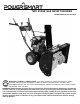
TWO STAGE GAS SNOW THROWER MODEL DB7651A-24, 26 and 28 Questions, problems, missing parts? If you have questions or need technical support, call the Amerisun customer service department at 1-800-791-9458 or visit Amerisuninc.com and e-mail support@amerisuninc.com. For engine related problems, questions and warranty service call the engine manufacturer 1-877-274-2214. WARNING! Read and follow all safety rules and instructions in this manual before attempting to operate this machine.
TABLE OF CONTENTS Safety....................................................................................................................................................... 2 Feature Identification ................................................................................................................................ 6 Box Contents ............................................................................................................................................ 7 Assembly ...............
SAFETY This symbol points out important safety instructions which, if not followed, could endanger the personal safety and or property of yourself and others. Read and follow all instructions in this manual before attempting to operate this machine. Failure to comply with these instructions may result in personal injury. WARNING! This machine was built to be operated according to the safe operation practices in this manual.
• Exercise caution to avoid slipping or falling, especially when operating in reverse. • Stay alert, watch what you are doing and use common sense when operating your Snow Thrower. • Do not use your Snow Thrower while you are tired or under the influence of drugs, alcohol, medication. A moment of inattention while operating the Snow Thrower may result in severe bodily injury. • NEVER LEAVE YOUR RUNNING SNOW THROWER UNATTENDED. Stop the engine.
• If the machine should start to vibrate abnormally, stop the engine, disconnect the spark plug wire and ground it against the engine.Inspect thoroughly for damage. Repair any damage before starting and operating. • Disengage all control levers and stop engine before you leave the operating (behind the handles). • Wait until the auger /impeller comes to a complete stop before unclogging the chute assembly, making any adjustments, or inspections. • Never put your hand in the discharge or collector openings.
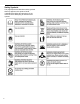
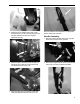
Safety Symbols This page depicts and describes safety symbols that may appear on this product. Read, understand and follow all instructions on the machine before attempting to assemble and operate.
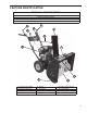
FEATURE IDENTIFICATION TECHNICAL SPECIFICATIONS Clearing Width: DB7651A 24, 26 and 28 inches Clearing Height: 21 inches 4 Forward and 2 Reverse Speeds Engine Displacement: 208cc, 4 stroke A K C B J D E I F A - Drive Control Handle B - Speed Control Lever C - Auger Control Handle D - Chute Rotation Handle E - Engine F - Skid Shoe G - Augers H - I mpe l l er G H I - Snow/Ice Clean Out Tool J - Chute Assembly K - Chute Deflector Lever - 6
A. Drive Control Handle K. Chute Deflector Lever Located on the right side of the upper handle, the Drive Control is used to engage and disengage the drive wheels. Squeeze the Drive Control handle against the upper handle to engage the wheels; release to disengage. B. Speed Control Lever The angle of the chute deflector controls the discharge distance of the snow. Raising the angle will increase the distance . Lowering the angle will decrease the distance.
2. Attach the chute rotation bar to the mount bracket onto the chute housing using two hex screws, washers and locknuts. Tighten fasteners securely. 3. Slide the upper chute crank rod through the mounting hole under the control panel and into the lower chute crank rod. NOTICE: Make sure all fasteners are tightened before starting the machine. Handle Assembly 1. Attach the lower handles using four (4) bolts. Each side will require two (2) bolts. 2.
NOTICE: Do not bend or kink the control cables. The cables should be routed under the handle assembly and not wrapped around the handle or knobs. The cables must move freely and not bind. 3. Secure the speed control cables to the handle with provided clips. Note: Do not secure the auger or drive control cables with the clips. avoid dirt and gravel from entering the auger. The optimal height of the plate will vary depending on the type of surface being cleared.
• Start your clearing path by throwing snow in a back and forth motion. To clear in the opposite direction, stop your Snow Thrower and pivot it on its wheels to face the opposite direction. Make sure to overlap clearing paths. • Determine the direction of the wind. If possible, move in the same direction as the wind so that the snow is not thrown against the wind, back into your face and on the just cleared path.
Drive Speed Control Lever Chute Discharge Angle Adjustment Move the drive speed control lever to the desired speed. There are six (6) settings: four (4) forward speeds and two (2) reverse speeds. 1 is the slowest forward speed and 4 is the fastest forward speed. R1 is the slowest reverse speed and R2 is the fastest reverse speed. WARNING! Always disengage the drive and auger control handles before making adjustments. Make sure the augers are stopped and the machine is not moving.
OPERATING YOUR SNOW THROWER Starting move or throw. Wet snow will tend to clog and stick more to the augers and chute. Keep the auger engaged as much as possible when clearing wet snow to help prevent clogging. Please refer to ENGINE manual (separate document) for engine operation instructions. WARNING! If snow is filled with foreign material, damage to the snow thrower may result. Avoid snow with foreign materials.
Check the bolts at frequent intervals for proper tightness to ensure that the equipment is in safe working condition. After each snow removal session, run the Snow Thrower for a few minutes to prevent the collector/impeller from freezing. Stop the engine, wait for all revolving parts to stop completely, and wipe residual ice and snow off the unit. Rotate the chute rotation handle several times to remove any excess snow.
Auger Shear Pin Replacement Shear pins are used to attach the auger shaft to the auger blades. A clog or jam in the augers may cause one or multiple shear pins to break. The shear pins are a safety mechanism and designed to break under high load or impact to protect the auger drive system from damage. Replacement shear pins and nylon locknuts are provided with your snow thrower. For additional replacement shear pins, please call the customer service department. 1.
To adjust the cables one cable should be moved up and the other down equally in their respective brackets until there is a positive direction change when the lever is shifted between F1 and R1. The middle position between these two settings is neutral (there is no actual neutral "notched" position on the control panel) Note: The upper cable end must be in the upper single center hole of the adjustment plate. Do not change the position of the upper cable. 5. Connect the upper cable to the control handle. 6.
Auger Belt Tension Adjustment WARNING! Entanglement Hazard - Before performing any adjustment procedures, make sure the engine is off and remove the spark plug wire from the spark plug to ensure the engine cannot accidently start. Never adjust belt tension with the engine running. The auger cable is located on the left side (when standing behind the snow blower) and is made up of an upper and lower cable connected by an adjustment plate.
4. Adjustment is made by changing the position of the lower cable in the adjustment plate holes (1 to 9). Only move the lower cable diagonally one hole at a time from its original position. Note: The upper cable end must be in the upper single center hole of the adjustment plate. Do not change the position of the upper cable. 5. Connect the upper cable to the control handle. 6. Start the engine and engage the auger to test the operation of the auger.
5. Right Side - Remove the hex nuts, lock washers and flat washers attaching the auger housing to the main frame. 6. Remove the belt from the drive pulley while pulling the right side of the auger housing away from the main frame just enough to access the belt and auger pulley. 7. Push the auger tension pulley arm to move the auger brake, away from the belt to allow removal of the belt. 1 – Auger Brake 8. Remove the auger belt.
2. Push the auger tension pulley arm to move the auger brake to allow access for installation of the belt into the auger pulley. 1 – Auger Brake 3. Route the belt to the inside of the tension pulley and install the auger belt onto the drive pulley while pulling the auger housing into position with the main frame. Note: The belt guide pin helps keep the belt in the pulley when the belt is disengaged. The pin should not be tight to the belt.
Auger Belt and Related Component Inspection When replacing your snow blower auger belt it is important to determine the cause of the failure (if applicable) and take corrective action to avoid repeated failure.
TROUBLESHOOTING Problem Possible Causes Remedy WARNING - Before attempting to make any inspections, repairs or adjustments, stop the engine, wait for all moving parts to stop moving and carefully disconnect the engine spark plug wire. If tipping or turning the snow blower is required for any inspection or repair, first wait until the engine is cool to the touch and then drain the engine of all fuel and oil into suitable containers and store or dispose of in a proper manner.
Drive System No forward or reverse drive movement when drive handle engaged Drive speed control stuck in gear or wont change gears Drive speed control allows only one direction forward or reverse Drive engaged when drive control handle released 1 Drive control cable loose, broken or binding 1 Repair or adjust drive control cable and adjust tension, see Auger and Drive Cable Adjustment 2 Drive belt loose or damaged 2 Check drive belt tension pulley for damage or incorrect tension, repair as necessary.
WARRANTY TWO YEAR WARRANTY ENGINE WARRANTY See the ENGINE manual included with this snow thrower for engine warranty information. For all engine related warranty issues contact LCT engine corporation - phone 1-877-274-2214. WARRANTY For two years from date of retail purchase within U.S.A., the manufacturer will, at its option, repair or replace, for the original purchaser, free of charge, any part or parts found to be defective in material or workmanship.