INSTRUCTION MANUAL EN 24 inch Two Stage Gas Snow Thrower FR 24 inch Souffleuse à Neige à Deux Phase ES Quintanieves De Gas De 24 Pulgadas Con Dos Etapas Model # PSSHD24 Have product questions or need technical support? Please feel free to contact us! Website: www.Amerisuninc.com www.PowerSmartUSA.com Toll free: 1-800-791-9458 Mon-Fri 9-5 EST Email: support@amerisuninc.
TABLE OF CONTENTS Technical data...................................................................................................3 Introduction...................................................................................................... 4 Safety information............................................................................................ 4 Knowing your snow thrower............................................................................10 Assembly and adjustments.....................
INTRODUCTION Thank you for purchasing a PowerSmart® Product. This manual provides detailed information regarding the safe operation and maintenance of this product. Every effort has been made to ensure the accuracy of the information in this document. PowerSmart® reserves the right to change this product and specifications at any time without prior notice. Please keep this manual available to all users during the entire life of the product.
TRAINING Read, understand, and follow all instructions on the machine and in the manual(s) before attempting to assemble and operate. Keep this manual in a safe place for future and regular reference. • Be familiar with all controls and their proper operation. Know how to stop the machine and disengage them quickly. • Never allow children under 14 years of age to operate this machine.
PERSONAL SAFETY • Engine exhaust, and certain vehicle components contain or emit chemicals known to cause cancer, birth defects or other reproductive harm. • Read, understand and follow all instructions on your snow thrower unit and in this instruction manual before attempting to assemble and operate your machine. • Keep this instruction manual in a safe place for future and regular reference.
• Never over fill fuel tank. • Replace gasoline cap and tighten securely. • If gasoline is spilled, wipe it off the engine and equipment. Move machine to another area. Wait 5 minutes before starting the engine. • Never store the machine or fuel container inside where there is an open flame, spark or pilot light (e.g. furnace, water heats, space heater, clothes dryer etc.). • Allow machine to cool at least 5 minutes before storing.
• Plan your snow-throwing pattern to avoid snow discharge towards windows, walls, cars etc., thus avoiding possible property damage or personal injury caused by a ricocheting debris. • Never direct discharge at children, bystanders and pets or allow anyone in front of the machine. • Do not overload machine capacity by attempting to clear snow at too fast of a rate…. Remember! Slow and steady operation is best to avoid clogs of snow being impelled too rapidly.
• • • • • • • • • • • • • This process will keep the machine in safe working condition. Also, visually inspect machine for any damage. Verify that the auger gearbox, located between your right and left auger blades, has substantial lubricant in the casing. The gearbox fill and drain plugs (bolts) are the only “vertical” plugs (bolts) on the gearbox assembly when viewed in the standing position. The top plug (bolt) is used for filling…the bottom plug (bolt) is for draining.
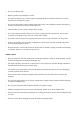
KNOWING YOUR SNOW THROWER Use the illustrations below to become familiar with the locations and functions of the various components and controls of this snow thrower.
19 20 19 20 21 22 Fuel Tank Cap Primer Bulb 21 22 Switch Key Choke Lever Drive Control Lever Located on the right side of the upper handle, the Drive Control Handle is used to engage and disengage the drive wheels. Squeeze the Drive Control Handle against the upper handle to engage the wheels; release to disengage. Drive Speed/Gear Control The Speed/Gear Control is located on the center of the panel and is used to set the drive speed and direction of travel.
ASSEMBLY ANDADJUSTMENTS The following section describes steps necessary to prepare the snow thrower for use. If after reading this section, you are unsure about how to perform any of the steps please call (800) 791-9458 Mon-Fri 9-5 EST for customer service assistance. Failure to perform these steps properly can damage the snow thrower. Unpacking Unpack the snow thrower and all its parts, and compare against the list below. 1. Snow Thrower 2. Discharge Chute Assembly 3. Chute Rotation Handle 4. (Qty.
Step 2: Installing the Upper Handle 1. When installing the Upper Handle, please note that the Drive & Auger Cables will already be pre-attached to Upper Handle. 2. Attach Upper Handle using the Frame Handle Assembly Hardware (4 sets /Knob, Saddle Washer, M8 Nut, T-Screw) for your Upper & Lower Handle connection. 3. When attaching Assembly Hardware, make sure ALL cables are underneath the Frame (Upper & Lower) Handles after installation as indicated in Figure 3.
Step 3: Installing Speed Control Connection Rod 1. 2. Install the connection rod to the hole in the Frame as indicated on Figure 4 -1. Install another side of connection rod to the hole in the trigger as indicated on Figure 4-2. Fig.4-2 Fig.
Step 4: Installing The Chute Assembly 1. Insert Lower Discharge Chute/Support Tube Assembly into the designated Chute opening for the Lower Discharge Chute, while inserting the Support Tube into the designated base of the Frame. (See Figure 5). 2. Secure Support Tube to base with (2) Screws and nuts provided. Figure 5 Step 5: Installing the Chute Handle 1. Slide Chute Handle through Chute Handle Guide near the Upper Panel, as indicated on Figure 6. 2.
3. Verify that ALL cables are clear and not obstructing the Chute Handle operation of your snow thrower unit. Clip the cable into the hook. (See Figure 7) Figure 7 Step 6-Installing Clean Out Tool 1.
Step 7 – Skid shoes installation and adjustments 1. Locate the set of skid shoes from parts bag and remove the bolts. 2. Loosely install the skid shoes using the bolts and hex nuts as shown on each side of the auger housing. Make sure the skid shoe tip faces out. Adjustment of the skid shoes sets the height above the ground at which the auger shave plate operates.
SNOW THROWER PREPARATION ADD OIL The snow thrower is shipped without oil. User must add the proper amount of oil before operating the snow blower for the first time. The oil capacity of the engine crankcase is 16 fl. oz. For general use, we recommend 5W-30, 4-stroke engine oil. ENGINE OIL RECOMMENDATIONS Select good quality detergent oil bearing the American Petroleum Institute (API) service classifications SJ, SL, or SM (synthetic oils may be used).
• NOTE: After completing the above preparation, the engine is ready to be started. WARNING! Keep the area of operation free from foreign objects that can be thrown by the auger and/or impeller blades. Perform a thorough inspection of the area since some objects may be hidden from view by surrounding snow. If the snow thrower hits an obstruction or picks up a foreign object during use, stop the snow thrower immediately, remove the obstruction, and inspect it for damage.
3. When finished clearing a snow path, release the auger control lever (handle) and the drive control lever (handle). L Drive Control Lever (Handle) Auger Control Lever (Handle) R Attention: Release (disengage) the auger and drive control lever (handles) before adjusting the drive speed control lever. NEVER change the drive/gear speed while your snow thrower is in motion, as it will damage the drive mechanism and void the warranty.
OPERATING YOUR SNOW THROWER MANUAL START THE ENGINE To manual start the engine, perform the following steps: 1. Check the oil and fuel levels. 2. Move the choke lever to the “CLOSE” position. 3. Make sure insert the switch key. 4. Press the primer bulb 3 times. 5. Pull on the recoil starter handle slowly until a slight resistance is felt, then pull quickly to start the engine. Return cord gently into the recoil starter. Never allow the cord to snap back. 6. If engine fails to start, repeat step 4.
3. Engage/depress the drive control lever (handle) and direct the snow thrower into the snow to be cleared. NOTICE: NEVER change speed/gear positions while the drive control lever (handle) is engaged. Disengage the drive control handle BEFORE changing speeds or directions. If the snow is deeper than the height of the auger, remove it in several steps taking narrower swaths. Make several passes with the auger overlapping the cleared areas and reduce forward speed.
MAINTENANCE PROCEDURES TIRE INFLATION Before each use of your Snow Thrower, check the tire pressure. The pressure in each tire should be in the range of 20-24 psi for the best performance. The pressure can be checked using an ordinary tire pressure gauge. Fill the tires using a small or pressure regulated air compressor. WARNING! DO NOT OVER-INFLATE THE TIRES. Over-inflating could cause a tire to burst and cause severe bodily injury.
NOTICE: Never replace the shear pins with standard pins or fasteners. Damage may occur to the snow blower and drive systems. DRIVE SPEED CONTROL ADJUSTMENT The speed/gear control lever is connected to connection rod that work in tandem to control machine speed and direction. Upper Nuts Lower Nuts Depending on if the connection rod setting towards forward or reverse, adjustment of the connection rod will vary.
3. Loosen the belt guide pin hex screw (installed on engine crankcase) and rotate the pin away from the pulley. Screw Step 1 Step 2 Step 3 4. Left Side - Loosen the hex nuts attaching the auger housing to the main frame. 5. Right Side - Remove the hex nuts, lock washers and flat washers attaching the auger housing to the main frame. 6. Remove the belt from the drive pulley while pulling the right side of the auger housing away from the main frame just enough to access the belt and auger pulley. 7.
Note: The belt guide pin helps keep the belt in the pulley when the belt is disengaged. The pin should not be tight to the belt. The pin should be loose enough to allow the belt to spin freely but not allow the belt to jump off the pulley. 5. Connect the upper cable to the auger control handle. 6. Install belt cover using (Qty. 2) hex screws. WARNING! Ensure the belt cover is installed and all safety guards are in place before the engine is started and at all times when the engine or machine are operating.
STORAGE & CLEANING PROPER STORAGE PROCEDURES WARNING! Never store your snow shrower for extended periods of time with fuel in the tank or carburetor. Fuel stabilizer can be added to the fuel in can to extend its shelf life for storage. Store the unit in a locked, dry place out of the reach of children to prevent unauthorized use or damage. Cover loosely with a tarp for added protection. CLEANING 1. To clean your Snow Thrower, use a damp cloth and mild detergent on the surfaces only.
TROUBLESHOOTING Problem Causes Remedy WARNING - Before attempting to make any inspections, repairs or adjustments, stop the engine, wait for all moving parts to stop moving and carefully disconnect the engine spark plug wire. If tipping or turning the snow blower is required for any inspection or repair, first wait until the engine is cool to the touch and then drain the engine of all fuel and oil into suitable containers and store or dispose of in a proper manner.
Problem Causes Remedy Drive system No forward or reverse drive movement when drive handle engaged Drive speed control stuck in gear or won’t change gears Drive speed control allows only 1 direction Drive engaged when drive control handle released Check drive belt tension pulley for damage or incorrect tension, repair as necessary. Replace drive belt.
Problem Auger System Auger belt broken, or repeated failure Auger rotating when auger control handle released Causes Remedy Auger tension pulley arm return spring broken or missing Replace tension arm return spring Auger tension pulley arm stuck or binding Repair or replace tension arm as necessary Auger tension pulley arm or pulley misaligned or damaged Repair, replace or align tension arm and or pulley as necessary Foreign material on pulleys and belt, oil, grease, dirt etc.
EXPLODED VIEW AND PARTS LIST Panel Assembly Item Stock# Description Qty Item Stock# Description 1 303020498 Hex Flange Screw M8X18 4 2 303080555 Lower Handle 3 303020461 4 21 203070105 Handle Cover 2 1 22 303181183 Left Operation Trigger 1 Washer Φ8 4 23 303010193 Screw 6×16 3 303043010 T-screw M8×55 4 24 303042042 Flat Washer φ6×φ16×2 3 5 203020336A Knob 4 25 303160746 Cushion Cover 3 6 303030066 Nut M8 4 26 303071343 DB7109 Gear Plate 1 7 303200050
Chute Assembly Item Stock # Description Qty Item Stock # Description 1 203050514 Chute 1 2 303030087 Hex Flang Lock Nut M6 3 303071344 4 20 303181164 Small Support Tube Welded 1 1 21 303030077 Locknut M8 1 Cable Seat 1 22 303130325 Pressure Spring φ3 1 303020244 Hex Flang Bolt M6×14 1 23 303071056 Locating Plate 1 5 303200117 Chute Cable 1 24 303020165 Square Bolt M8X55 1 6 303030077 Hex Flang Lock Nut M8 2 25 303020246 Bolt M6X16 2 7 303020622 Bolt
Frame Assembly 31
Item Stock # Description Qty Item Stock # Description Qty 2 1 9999960501 Engine 212CC 1 41 303100051 Grooved Deep Groove Ball Bearing 2 303160192 Small Tensioning Plate Spacer 1 42 303160799 Six Square Axis 1 3 303070202 Small Tensioning Plate 1 43 303042004 Flat Wsher Φ10*Φ22*2 2 4 303042005 Flat Washer φ8×φ28×3 1 44 303343043 Locknut M10 1 5 303020279 Outer Hex Flange Bolt M8×25 1 45 303525287 Big Bottom Plate 1 6 303030077 Flange Locknut M8 1 46 3035860
Auger Housing Assembly 33
Item Stock# 1 303020245 2 Description Qty Item Hex Flange Bolt M8X14 6 29 303020332 Bolt M8×14 4 303070234 Bearing Block 2 30 303181158 Impeller 1 3 203060013 Plastic Bearing 2 31 303030032 Lock Nut M6 2 4 203060012 Auger Sleeve 8 32 303020442 Hex Washer Bolt φ6×35 2 5 303180409 Right Auger Welding 2 33 303020166 Bolt M8×18 4 6 203050108 Spacer Bush 1 4 34 303070197 Skid Shoes 2 7 203050109 Spacer Bush 2 8 35 303030077 Flang Lock Nut M8 4 8 30213
Engine Explode View and Bom List 35
Item Stock# Description Stock# Description Qty 1 303020444 57 9534960101 Split cotter 1 2 1 58 9158960301 Camshaft assembly 1 3 muffler pipe 1 59 9158960501 Bearing 2 9245960103 Cylinder Head Cover Gasket 1 60 9122960501 Crankshaft assembly 1 5 303020382 Screw M6X12 2 61 9438960101 Speed regulating driven gear combination 1 6 9143960101 Air lock nut 2 62 9140960103 Location pin 1 9143960102 Valve clearance adjusting nut 2 63 303020382 Bolt M6X12 2 1 4
45 9140960102 Location pin 2 101 9529960301 Fuel tank assembly 46 9113960102 47 9113960101 48 9564960501 49 9146960501 50 9129960501 51 9140960501 52 53 Exhaust valve 1 102 9121960101 Governing gear shaft 1 Intake valve 1 103 303043040 Washer 2 Piston ring assembly 1 104 9092960101 Slide bushing 1 Gudgeon pin circlip 2 105 303020382 Bolt M6X12 2 Piston 1 106 9221960101 Flywheel side housing 1 Piston pin 1 107 9247960101 O-ring 1 9221960102 Fairwater
TWO (2) YEARS LIMITED WARRANTY PowerSmart is committed to building tools that are dependable for years. Our warranties are consistent with our commitment and dedication to quality. TWO (2) YEARS LIMITED WARRANTY OF POWER SMART PRODUCTS FOR HOME USE. PowerSmart (“Seller") warrants to the original purchaser only, that all PowerSmart consumer power tools will be free from defects in material or workmanship for a period of two (2) years from date of purchase.
39