CUSTOMER SERVICE (USA) 1-877-617-3501 SERVICIO AL CLIENTE (Mexico) 01 800 843 1111 OPERATOR’S MANUAL MANUAL DEL OPERADOR 6,800 WATT GENERATOR GENERADOR 6 800 WATTS www.powerstroketools.com To register your POWERSTROKE product, please visit: http://register.powerstroketools.com/ Para registrar su producto de POWERSTROKE, por favor visita: http://register.powerstroketools.
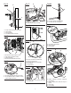
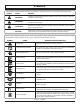
See this fold-out section for all of the figures referenced in the operator’s manual. Consulte esta sección desplegable para ver todas las figuras a las que se hace referencia en el manual del operador. Fig.
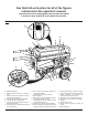
Fig. 2 10 5 6 21 20 16 19 7 4 9 12 11 8 OR (O) 23 3 13 2 16 22 1 15 14 Fig. 3 18 18 17 8 C A - Socket wrench (llave de casquillo) B - Combination wrench (llave de combinación) C - Phillips screwdriver (destornillador Phillips) A B Fig. 4 Fig. 5 A A Fig.
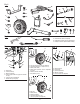
Fig. 7 Fig. 10 C A Fig. 12 A OFF B A - Lanyard (correa) B - Handle lock pin (pasador de seguro del mango) C - Frame (armazón) Fig. 8 B A B B A - Oil cap/dipstick (tapa de relleno de aceite/ varilla medidora de aceite) B - Oil fill hole (agujero de llenado de aceite) Fig.
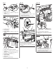
Fig. 14 Fig. 17 A A Fig. 21 B B D A OFF C A - Fuel line (conducto de combustible) B - Fuel filter (filtro de combustible) A - Spark plug (bujía) B - Spark plug cap (tapa de la bujía) B ABCD- Fig. 22 Fig. 18 A Engine switch (interruptor del motor) Off (apagado) Start (arranque) Lock button (botón del seguro) Fig. 15 B C C Fig. 19 A B C A - Fuse holder (portafusibles) B - Spring (resorte) C - Fuse (fusible) OFF Fig.
TABLE OF CONTENTS Introduction..................................................................................................................................................................... 2 Important Safety Instructions......................................................................................................................................3-4 Specific Safety Rules...................................................................................................................
IMPORTANT SAFETY INSTRUCTIONS DANGER: Carbon Monoxide. Using a generator indoors CAN KILL YOU IN MINUTES. Generator exhaust contains high levels of carbon monoxide (CO), a poisonous gas you cannot see or smell. If you can smell the generator exhaust, you are breathing CO. But even if you cannot smell the exhaust, you could be breathing CO. Never use a generator inside homes, garages, crawlspaces, or other partly enclosed areas. Deadly levels of carbon monoxide can build up in these areas.
IMPORTANT SAFETY INSTRUCTIONS Use only authorized replacement parts and accessories and follow instructions in the Maintenance section of this manual. Use of unauthorized parts or failure to follow maintenance instructions may create a risk of shock or injury. Maintain the unit per maintenance instructions in this Operator’s Manual. Inspect the unit before each use for loose fasteners, fuel leaks, etc. Replace damaged parts.
SYMBOLS The following signal words and meanings are intended to explain the levels of risk associated with this product. SYMBOL SIGNAL MEANING DANGER: Indicates an imminently hazardous situation, which, if not avoided, will result in death or serious injury. WARNING: Indicates a potentially hazardous situation, which, if not avoided, could result in death or serious injury. CAUTION: Indicates a potentially hazardous situation, which, if not avoided, may result in minor or moderate injury.
SYMBOLS Some of the following symbols may be used on this product. Please study them and learn their meaning. Proper interpretation of these symbols will allow you to operate the product better and safer. SYMBOL NAME DESIGNATION/EXPLANATION A Amperes Current Hz Hertz Frequency (cycles per second) W Watt Power hrs Hours Time gal Gallon Volume qt Quart Volume SAFETY LABELS The information below can be found on the generator.
SYMBOLS FUEL WARNING No smoking when filling with gasoline. Do not overfill. Full level is 1 in. below the top of the fuel neck. Stop the engine for five minutes before refueling to avoid the heat from the muffler igniting fuel vapors. ENGINE LUBRICANT WARNING You must add lubricant before first operating the generator. Always check the lubricant level before each operation. The lubricant level should always register between the hatched areas on the dipstick.
ELECTRICAL EXTENSION CORD CABLE SIZE Refer to the table below to ensure the cable size of the extension cords you use are capable of carrying the required load. Inadequate size cables can cause a voltage drop, which can burn out the appliance and overheat the cord. Load in Watts Current in Amperes At 120V At 240V 2.5 300 5 Maximum Allowable Cord Length #8 Wire #10 Wire #12 Wire #14 Wire #16 Wire 600 1000 ft. 600 ft. 375 ft. 250 ft. 600 1200 500 ft. 300 ft. 200 ft. 125 ft. 7.
ELECTRICAL GENERATOR CAPACITY Make sure the generator can supply enough continuous (running) and surge (starting) watts for the items you will power at the same time. Follow these simple steps. 1. Select the items you will power at the same time. 2. Total the continuous (running) watts of these items. This is the amount of power the generator must produce to keep the items running. See the wattage reference chart at right. 3. Estimate how many surge (starting) watts you will need.
FEATURES PRODUCT SPECIFICATIONS ENGINE Engine Type..........................................GX390, 389cc, OHV Fuel Volume................................................................. 8 gal. Starting Watts...........................................................8500 W Rated Frequency.........................................................60 Hz GENERATOR Rated Voltage......................................................120V/240V Rated Amps...................................................... 56.
ASSEMBLY UNPACKING This product requires assembly. Carefully cut the box down the sides then remove the machine and any accessories from the box. Make sure that all items listed in the loose parts list are included. NOTE: This machine is heavy and requires a minimum of two people to lift. To avoid back injury, lift with your legs and not your back. WARNING: Do not use this product if any parts on the Loose Parts List are already assembled to your product when you unpack it.
ASSEMBLY INSTALLING THE FRAME SUPPORT See Figure 4. Install the frame support on the bottom of the generator frame on the same side as the handle. Locate the following items: Frame support 2 lock nuts (5/16-18) 4 large washers (5/16 in.) 2 bolts (5/16-18 x 1 in.
ASSEMBLY RELEASING THE HANDLES CONNECTING/DISCONNECTING BATTERY Remove the handle lock pins and lower the handles to the down position. See Figure 9. The battery cables must be connected before the electric start feature of the generator can be operated. To connect battery cables: WARNING: To reduce the risk of electrocution or explosion, do not short circuit the battery terminals or charge in a sealed container. Keep sparks and flame away. WARNING: Keep metal objects away from the battery terminals.
OPERATION BEFORE OPERATING THE UNIT Always position the generator on a flat firm surface. Mix fuel stabilizer and gasoline prior to filling the tank by using a gas can or other approved fuel container and shaking gently to combine. NOTE: To control the amount of fuel stabilizer being added to the engine, always mix fuel stabilizer with gasoline before fueling the tank rather than adding fuel stabilizer directly into the generator’s fuel tank.
OPERATION ELECTRIC START This generator model is provided with both electric start and recoil start capabilities. Avoid prolonged cranking, as it can damage the engine. The battery provided is a nominal 12 volt sealed rechargeable lead-acid battery and can be operated in any position without leakage. It complies with non-spillable battery regulations. Its convenient size offers a 30% reduction over conventional batteries. NOTE: Brand new generators are shipped with the battery connections disconnected.
MAINTENANCE WARNING: When servicing, use only identical replacement parts. Use of any other parts could create a hazard or cause product damage. Only the parts shown on the parts list are intended to be repaired or replaced by the customer. All other parts should be replaced at an authorized service center. GENERAL MAINTENANCE Keep the generator in a clean and dry environment where it is not exposed to dust, dirt, moisture, or corrosive vapors.
MAINTENANCE When the fuel has drained from the tank, close the fuel valve and reinstall fuel line securely on petcock. DRAINING THE CARBURETOR Turn the engine switch OFF ( O ). Turn the fuel valve to the OFF position. Position a suitable container under the carburetor drain screw to catch fuel; loosen the screw. Allow fuel to drain completely into container. Retighten drain screw. NOTE: Consult hazardous waste management guidelines in your area for the proper way to dispose of used fuel.
MAINTENANCE STORAGE When preparing the generator for storage, allow the unit to cool completely then follow the guidelines below. STORAGE TIME PRIOR TO STORING Less than 2 months Drain gasoline from tank and dispose of in a suitable container according to state and local o rdinances. 2 months to 1 year Drain fuel from carburetor. Drain gasoline from tank and dispose of in a suitable container according to state and local o rdinances. 1 year or more Drain fuel from the carburetor.
TROUBLESHOOTING PROBLEM Engine will not start. POSSIBLE CAUSE SOLUTION Engine switch is OFF. Turn engine switch to ON. No fuel. Fill fuel tank. Stale gasoline or water in gasoline. Drain entire system and refill with fresh fuel. Lubricant level is low. Engine is equipped with Low Oil Shutoff. If engine lubricant level is low, it must be filled before unit will start. Check engine lubricant level and fill, if necessary. Fuel valve is OFF. Turn fuel valve ON.
WARRANTY LIMITED WARRANTY WARRANTY COVERAGE OWT Industries, Inc., (the Company) warrants to the original retail purchaser that this PowerStroke Product is free from defects in material and workmanship and agrees to repair or replace, at the Company’s sole discretion, any defective Product free of charge within these time periods from the date of purchase: Three years, if the Product is used solely for personal, family, or household use; One year, if the Product is used for business or commercial use.
WARRANTY OWT INDUSTRIES, INC., CALIFORNIA AND FEDERAL EMISSION CONTROL WARRANTY STATEMENT YOUR WARRANTY RIGHTS AND OBLIGATIONS The California Air Resources Board, U.S. EPA, Environment Canada, and OWT Industries, Inc., are pleased to explain the evaporative emission control system’s warranty on your 2013/2014 small off-road equipment. In California, new equipment that uses small off-road engines must be designed, built, and equipped to meet the State’s stringent anti-smog standards. OWT Industries, Inc.
TABLA DE MATERIAS Introducción.................................................................................................................................................................... 2 Instrucciones de seguridad importantes.....................................................................................................................3-4 Reglas de seguridad específicas....................................................................................................
INSTRUCCIONES DE SEGURIDAD IMPORTANTES PELIGRO: Monóxido de carbono. Usar un generador en el interior LO MATARÁ EN POCOS MINUTOS. Los gases de escape del generador contienen niveles altos de monóxido de carbono (CO), un gas venenoso que no puede verse ni olerse. Si puede oler los gases de escape del generador, está respirando CO. Pero incluso si no puede oler los gases de escape, es posible que esté respirando CO.
INSTRUCCIONES DE SEGURIDAD IMPORTANTES Los generadores fijos instalados de manera permanente son la mejor alternativa para abastecer de electricidad al hogar durante los cortes de energía. Incluso los generadores portátiles que están conectados correctamente pueden sobrecargarse. De esta manera, los componentes del generador pueden recalentarse o exigirse demasiado, lo que podría producir una falla en el generador.
SÍMBOLOS Las siguientes palabras de señalización y sus significados tienen el objeto de explicar los niveles de riesgo relacionados con este producto. SÍMBOLO SEÑAL SIGNIFICADO PELIGRO: Indica una situación peligrosa inminente, la cual, si no se evita, causará lesiones graves o mortales. ADVERTENCIA: Indica una situación peligrosa posible, la cual, si no se evita, podría causar lesiones graves o mortales.
SÍMBOLOS Es posible que se empleen en este producto algunos de los siguientes símbolos. Le suplicamos estudiarlos y aprender su significado. Una correcta interpretación de estos símbolos le permitirá utilizar mejor y de manera más segura el producto.
SÍMBOLOS ADVERTENCIA DE COMBUSTIBLE No fume al abastecer el combustible. No llene de más. El nivel de lleno es 25 mm (1 pulg.) debajo del cuello del tanque de combustible. Pare la marcha del motor cinco minutos antes del reabastecimiento de combustible para evitar que el calor del silenciador encienda los vapores de combustible. ADVERTENCIA DEL LUBRICANTE DE MOTOR Antes de utilizar el generador debe abastecerlo de lubricante. Antes de utilizar la unidad, revise el nivel de lubricante.
ASPECTOS ELÉCTRICOS CALIBRE DEL CORDÓN DE EXTENSIÓN Consulte el cuadro mostrado abajo para asegurarse de que el calibre de los cordones de extensión que utilice puedan con la carga eléctrica requerida. Los cordones de calibre insuficiente pueden causar una caída de voltaje, lo cual puede quemar el dispositivo y recalentar el cordón mismo. Corriente en Carga en vatios Amperios A 120 V A 240 V Longitud máxima permitida del cordón Conduct. #10 Conduct. #12 Conduct. #14 Conduct. #16 2,5 300 600 Conduct.
ASPECTOS ELÉCTRICOS CAPACIDAD DEL GENERADOR Cerciórese que el generador pueda suministrar suficientes vatios de potencia continua (en marcha) y de sobrecorriente (al arrancar) para los equipos que desee alimentar al mismo tiempo. Siga estos pasos sencillos. 1. Seleccione los equipos que desea alimentar al mismo tiempo. 2. Sume la potencia continua (en marcha) en vatios de estos equipos. Esta es la cantidad de potencia que el generador debe producir para mantener en marcha los equipos.
CARACTERÍSTICAS ESPECIFICACIONES DEL PRODUCTO MOTOR Tipo de motor......................................GX390, 389 cc, OHV Fuel Volume.....................................................30,28 l (8 gal) Salida máxima.........................................................8 500 W Frecuencia nominal.....................................................60 Hz GENERADOR Voltaje nominal..................................................120V / 240V Amperaje nominal............................................
ARMADO DESEMPAQUETADO Este producto requiere armarse. Orte cuidadosamente los lados de la caja y después retire la herramienta y cualesquier accesorios de la caja. Asegúrese de que estén presentes todos los artículos enumerados en la lista de piezas sueltas. NOTE: Esta herramienta es pesada y requiere al menos de dos personas para levantarla. Para evitar una lesión en la espalda, levántela con sus piernas, no con su espalda.
ARMADO 4 arandela grande (5/16 pulg.) 2 perno (5/16-18 x 1 pulg.) Eleve el extremo del generador donde está ubicado el arrancador retráctil hasta una altura suficiente que permita el acceso a la parte inferior del bastidor; coloque firmemente cuñas debajo para apoyarlo. Alinee los agujeros del apoyo del bastidor con los agujeros del bastidor del generador.
ARMADO CONEXIÓN Y DESCONEXIÓN LA BATERÍA Cubra las terminales con las coberturas de caucho. Vea la figura 9. El cable de batería deben conectarse con la batería antes de que se ponga en marcha la función arranque eléctrico. Para conecte cable de batería: Conecte el cable rojo con la terminal positiva (+) y el cable negro con la terminal negativa (–). Asegúrese de que todas las conexiones estén firmes.
FUNCIONAMIENTO ANTES DE ACCIONAR LA UNIDAD USO DE ESTABILILZADOR DE COMBUSTIBLE Sólo utilícelo AL AIRE LIBRE y lejos de ventanas, puertas y respiraderos. El combustible se hace viejo, se oxida y descompone al paso del tiempo. Agregando estabilizador de combustible (no incluido) se prolonga la vida útil del combustible y se evita la formación de depósitos, los cuales pueden tapar el sistema del combustible.
FUNCIONAMIENTO SIEMPRE llene el tanque al aire libre y teniendo apagada la máquina. Retire la tapa de combusti ble. Llene el tanque de combustible hasta una altura de 25 mm (1 pulg.) abajo del cuello del tanque. Coloque de nuevo la tapa del tanque de combustible y asegúrela. NOTA: Siempre utilice gasolina sin plomo con un octanaje nominal inicial de 86 o mayor. Nunca utilice gasolina vieja, pasada o contaminada, y no utilice mezcla de aceite y gasolina.
MANTENIMIENTO ADVERTENCIA: Al dar servicio a la unidad, sólo utilice piezas de repuesto idénticas. El empleo de piezas diferentes podría causar un peligro o dañar el producto. Solamente las piezas enumeradas en la lista de piezas pueden ser reparadas o cambiadas por el consumidor. Todas las piezas restantes deben ser reemplazadas en un centro de servicio autorizado.
MANTENIMIENTO la suficiente capacidad para recibir el combustible drenado del tanque. Ponga la válvula de combustible en la posición ON (ENCENDIDO). Una vez que se haya drenado todo el combustible del tanque, cierre la válvula y vuelva a instalar el conducto en la llave de purga. DRENAJE DEL CARBURADOR Ponga el interruptor del motor en OFF ( O ) (APAGADO). Ponga la válvula de combustible en la posición OFF (APAGADO).
MANTENIMIENTO ALMACENAMIENTO Al preparar el generador para guardarlo, deje que la unidad se enfríe por completo y luego siga los lineamientos señalados abajo. TIEMPO DE ALMACENAMIENTO ANTES DE GUARDARLO Menos de dos meses V acíe el tanque de combustible y colóquelo en un recipiente apropiado según lo establecido por las disposiciones estatales y locales. De dos meses a un año Drene el combustible del carburador.
CORRECCIÓN DE PROBLEMAS PROBLEMA El motor no arranca. CAUSA POSIBLE SOLUCIÓN El interruptor del motor está en apagado (OFF). No hay combustible. Gasolina pasada o agua pasada en la gasolina. Está bajo el nivel de lubricante. Ponga el interruptor del motor en encendido (ON). Llene el tanque de combustible. Drene todo el sistema y reabastézcalo con combustible nuevo. El motor posee un apagado por poco aceite. Si el nivel del lubricante del motor es bajo, debe llenarse antes de que la unidad arranque.
GARANTÍA GARANTIA LIMITADA COBERTURA DE LA GARANTÍA OWT Industries, Inc., (la Compañía) garantiza al comprador minorista original que este Producto PowerStroke carece de defectos en material y mano de obra, y acuerda reparar o reemplazar, a la entera discreción de la Compañía, cualquier Producto defectuoso sin cargo en los siguientes períodos a partir de la fecha de la compra: Tres años si el Producto se utiliza exclusivamente para fines personales, familiares o domésticos.
GARANTÍA DECLARACIÓN DE GARANTÍA DE CONTROL DE EMISIONES DE OWT INDUSTRIES, INC., DEL ESTADO DE CALIFORNIA Y REGULACIONES FEDERALES DERECHOS Y OBLIGACIONES DEL CONSUMIDOR SEGÚN LA GARANTÍA ser garantizada por un periodo no menor al tiempo restante de la garantía. La Junta de Recursos Atmosféricos de California (CARB), de la Dirección de protección ambiental (EPA) de EE.UU., de Medioambiente de Canadá (Environment Canada) y OWT Industries, Inc.
NOTES / NOTAS Page / Pàgina 22
BATTERY CHARGER FCC COMPLIANCE This device complies with Part 15 of the FCC Rules. Operation is subject to the following two conditions: (1) This device may not cause harmful interference, and (2) This device must accept any interference received, including interference that may cause undesired operation. WARNING: Changes or modifications to this unit not expressly approved by the party responsible for compliance could void the user’s authority to operate the equipment.
6,800 WATT GENERATOR GENERADOR 6 800 WATTS OPERATOR’S MANUAL PS907000 Series / Serie MANUAL DEL OPERADOR CALIFORNIA PROPOSITION 65 WARNING: This product, its exhaust, and other substances that may become airborne from its use may contain chemicals, including lead, known to the State of California to cause cancer, birth defects, or other reproductive harm. Wash hands after handling. CALIFORNIA - PROPUESTA DE LEY NÚM.