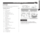
Model No. 71536 Owner's Manual 24" Router Table Fence Visit us on the web at www.powertecproducts.com You will need this manual for safety instructions, operating procedures, and warranty. Put it and the original sales invoice in a safe, dry place for future reference.
TABLE OF CONTENTS SECTION PRODUCT SPECIFICATIONS PAGE RECOMMENDED ROUTER BIT SPEEDS SAFETY RULES 1-2 BIT DIAMETER MAXIMUM SPEED Up to 1" (25 mm) . . . . . . . . . . . . . . . . . . . . . .22,000 -24,000 rpm Safety Rules 1" to 2" (25 mm–51 mm) . . . . . . . . . . . . . . . . 18,000-22,000 rpm 2" to 2-1/2" (51 mm–64 mm) . . . . . . . . . . . . 12,000-16,000 rpm PARTS AND CONTENTS 3 NOTE: Always follow bit manufacturer’s speed recommendations.
WARNING For your own safety, read all of the rules and precautions before operating tool. WARNING Always follow proper operating procedures as defined in this manual even if you are familiar with use of this router table fence or any tool used with this router table fence. Remember that being careless for even a fraction of a second can result in severe personal injury.
SAFETY RULES SPECIFIC SAFETY RULES 2 DANGER • To avoid serious injury, keep hands and fingers away from the spinning router bit. Be aware of the bit at all times. WARNING AVOID THIS SITUATION! 2 • BEFORE beginning any routing operation, ALWAYS make sure ALL knobs on the router table fence and accessories are tightened and the fence will not shift during use. • Always feed the workpiece against the rotation of the bit.
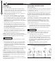
UNPACKING PARTS AND CONTENTS PARTS AND CONTENTS LISTS 3 Figure 1 Refer to Figure 1 Check for shipping damage. Check immediately whether all parts and accessories are included.
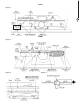
ASSEMBLY ASSEMBLY 4 4 ASSEMBLY ADJUSTING THE FENCE FACES Refer to Figure 2–4 Refer to Figure 5 • Remove the adhesive backing from the right to left tape measure and press into place. Start on the right end and carefully place the tape along the front edge of the fence. Use scissors to cut the excess tape from the left end. The two MDF adjustable fence faces are designed to slide about 2" along the fence. This allows the opening for the router bit to be adjusted from 0" up to 4".
ASSEMBLY BACK Figure 2 5 FRONT Figure 3 Figure 4 Figure 5
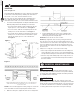
OPERATION OPERATION 6 JOINTING Figure 9 Refer to Figure 6–9 The independently adjustable fence faces allow the router table to be used as a vertical jointer by offsetting the outfeed fence face 3/128", 1/16", 5/64" from the infeed fence face. 6 Two sets of grooves are located in the fence behind the fence faces, slide the jointing rods into these grooves to offset the outfeed fence face 3/128", 1/16", 5/64" from the infeed fence face. 1. Loosen the round locking knobs securing the outfeed fence face.
NOTES NOTES 7 7
NOTES 8
WARRANTY WARRANTY 9 Thank you for investing in a POWERTEC power tool. This product has been designed and manufactured to meet high quality standards and is guaranteed for domestic use against defects in workmanship or material for a period of 12 months from the date of purchase. This guarantee does not affect your statutory rights. SOUTHERN TECHNOLOGIES LLC.
Southern Technologies, LLC Chicago, IL 60606