Owner's Manual Model No. 71655 32" Deluxe Router Table Fence System Visit us on the web at www.powertecproducts.com You will need this manual for safety instructions, operating procedures, and warranty. Put it and the original sales invoice in a safe, dry place for future reference.
TABLE OF CONTENTS SECTION PRODUCT SPECIFICATIONS PAGE RECOMMENDED ROUTER BIT SPEEDS SAFETY RULES 1-2 BIT DIAMETER Safety Rules MAXIMUM SPEED Up to 1" (25 mm). . . . . . . . . . . . . . . . . . . . . . 22,000 -24,000 rpm 1" to 2" (25 mm–51 mm). . . . . . . . . . . . . . . . . 18,000-22,000 rpm PARTS AND CONTENTS 3 2-1/2" to 3-1/2" (64 mm–89 mm). . . . . . . . . . .
WARNING For your own safety, read all of the rules and precautions before operating tool. WARNING Always follow proper operating procedures as defined in this manual even if you are familiar with use of this router table fence or any tool used with this router table fence. Remember that being careless for even a fraction of a second can result in severe personal injury.
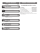
SAFETY RULES SPECIFIC SAFETY RULES 2 DANGER • To avoid serious injury, keep hands and fingers away from the spinning router bit. Be aware of the bit at all times. WARNING AVOID THIS SITUATION! 2 • Never use dirty, dull, or damaged router bits. Remove wood-resin build-up with a cleaner specifically formulated for cutting tools. Have dull bits sharpened by a qualified person. Discard damaged bits. • Make sure at least 75% of the router-bit shank length is securely held in the router collet.
UNPACKING Figure 1 Refer to Figure 1 3 PARTS AND CONTENTS PARTS AND CONTENTS Check for shipping damage. Check immediately whether all parts and accessories are included.
ASSEMBLY ASSEMBLY 4 4 ASSEMBLY ADJUSTING THE FENCE FACES Refer to Figure 2–4 Refer to Figure 5 • Remove the adhesive backing from the right to left tape measure and press into place. Start on the right end and carefully place the tape along the front edge of the fence. Use scissors to cut the excess tape from the left end. The two MDF adjustable fence faces are designed to slide about 2" along the fence. This allows the opening for the router bit to be adjusted from 0" up to 4".
ASSEMBLY BACK Figure 2 5 FRONT Figure 3 Figure 4 Figure 5
OPERATION OPERATION 6 JOINTING Figure 9-a Refer to Figure 6-9 The independently adjustable fence faces allow the router table to be used as a vertical jointer by offsetting the outfeed fence face 5/64", 1/16", 3/128" from the infeed fence face. 6 Two sets of grooves are located in the fence behind the fence faces, slide the jointing rods into these grooves to offset the outfeed fence face 5/64", 1/16", 3/128" from the infeed fence face.
NOTES GENERAL MAINTENANCE WARNING When servicing, use only identical replacement parts. Use of any other parts may create a hazard or cause product damage. To ensure safety and reliability, all repairs should be performed by a qualified service technician. 7 WARNING Keep the router table fence dry, clean, and free from oil and grease. Always use a clean cloth when cleaning. Never use brake fluids, gasoline, petroleum-based products or any strong solvent to clean the router table fence.
NOTES 8 8 NOTES
9 WARRANTY WARRANTY Thank you for investing in a POWERTEC power tool. This product has been designed and manufactured to meet high quality standards and is guaranteed for domestic use against defects in workmanship or material for a period of 12 months from the date of purchase. This guarantee does not affect your statutory rights. SOUTHERN TECHNOLOGIES LLC.
Southern Technologies, LLC Chicago, IL 60606