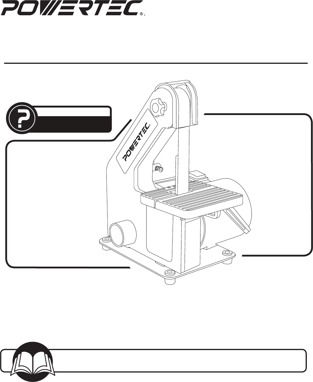
Model No. BD1030 Owner’s Manual 1" x 30" BELT SANDER QUESTION... 1•847•780•6120 Visit us on the web at www.southerntechllc.com You will need this manual for safety instructions, operating procedures, and warranty. Put it and the original sales invoice in a safe, dry place for future reference.
TABLE OF CONTENTS SECTION SAFETY RULES PRODUCT SPECIFICATIONS PAGE 1 Work Preparation Work Area Preparation Tool Maintenance Tool Preparation ASSEMBLY RPM . . . . . . . . . . . . . . . . . . . . . . . . . . . . . . . . . . . . . . 3260 2 PARTS ILLUSTRATION & LIST WARRANTY Belt Size . . . . . . . . . . . . . . . . . . . . . . . . . . . . . . . . 1" x 30" Belt Table Dimensions. . . . . . . . . . . . . . . . . . . . . . . 5" x 5" Dust Ports Diameter . . . . . . . . . . . . . . . . . . . . .
WARNING For your own safety, read and understand all warnings and operating instructions before using any tool or equipment. WARNING The 1" belt sander can be used for processing wood and metal products. However, combining both wood dust and metal filings can create a FIRE HAZARD. Make certain dust collector is free of wood dust deposits before processing metal products.
ASSEMBLY ASSEMBLY 2 UNPACKING Refer to Figure 1. Check for shipping damage. Check immediately whether all parts and accessories are included. • Take apart the locking lever assembly (hex headed bolt, washer, splined shaft, lever and screw with spring). Figure 3 Washer The sander comes assembled as one unit. Additional parts which need to be fastened to sander, should be located and accounted for before assembling.
Figure 7 Belt Tracking Knob WARNING Wheel ASSEMBLY To adjust sanding belt table: Sanding Belt To prevent trapping the workpiece or fingers between the table and the sanding belt adjust the sanding belt table to a maximum of 1/16" from the backstop. • Loosen the locking lever and set screw. Slide the sanding belt table in or out until it is 1/16" from the front of the sanding belt. See Figure 5. • Place a combination square on the table with the ruler side against the back stop.
ASSEMBLY BACKSTOP Figure 9 Refer to Figure 8 The backstop is a surface to sand against. The backstop can be removed for polishing and contour sanding. Bolt Flat Washer Sander Rubber Washer • Remove screws and washers securing backstop. Place screws, washers and backstop in a safe place for future use.
Ground Outlet Box Wire Size…………….. A.W.G. Up to 25 ft…………… 16 gauge NOTE: Using extension cords over 25 ft. long is not recommended. 3-Prong Plug ASSEMBLY Extension Cord Length Figure 10 MOTOR Grounding Prong WARNING Do not permit fingers to touch the terminals of plug when installing or removing from outlet. • Inspect tool cords periodically, and if damaged, have repaired by an authorized service facility.
OPERATION OPERATION 6 ON/OFF SWITCH SURFACE SANDING ON SANDING BELT Refer to Figure 13 Hold the workpiece firmly with both hands. Keep fingers away from sanding belt. Keep the workpiece end against the backstop and move it slowly across the sanding belt. Apply enough pressure to remove material; excessive pressure will reduce sanding efficiency. • To turn the sander ON, place the ON/OFF switch in the ON position. • To turn the sander OFF, place the ON/OFF switch in the OFF position.
SYMPTOM Sanding Grains easily rub off belt. POSSIBLE CAUSE(S) 1. Sanding belt has been stored in an incorrect environment. 2. Sanding belt has been damaged or folded. CORRECTIVE ACTION 1. Ensure sanding accessories are stored away from extremely hot or dry temperatures. 2. Store sanding accessories flat – not bent or folded. Deep sanding grooves or scars in workpiece. 1. Sanding belt grit is too coarse for the desired finish. 2. Workpiece sanded across the grain. 3.
8 PARTS LIST 8 1" x 30" BELT SANDER PARTS ILLUSTRATION
Key# Part# Description 1 2 3 4 4.1 4.2 4.3 4.4 5 5.1 5.2 5.3 5.4 6 7 8 9 10 11 12 13 14 15 16 17 18 BD1030001 BD1030002 BD1030003 BD1030004 BD1030004.1 BD1030004.2 BD1030004.3 BD1030004.4 BD1030005 BD1030005.1 BD1030005.2 BD1030005.3 BD1030005.4 BD1030006 BD1030007 BD1030008 BD1030009 BD1030010 BD1030011 BD1030012 BD1030013 BD1030014 BD1030015 BD1030016 BD1030017 BD1030018 18.1 18.2 18.3 18.4 19 20 21 22 23 24 BD1030018.1 BD1030018.2 BD1030018.3 BD1030018.
WARRANTY 10 WARRANTY Thank you for investing in a POWERTEC power tool. This product has been designed and manufactured to meet high quality standards and is guaranteed for domestic use against defects in workmanship or material for a period of 12 months from the date of purchase. This guarantee does not affect your statutory rights. 10 SOUTHERN TECHNOLOGIES LLC.
NOTE
NOTE
NOTE
Southern Technologies, LLC 3816 Hawthron CT, Waukegan, IL 60087