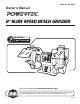
Model No. BGSS801 Owner’s Manual 8" SLOW SPEED BENCH GRINDER QUESTION... 1•847•780•6120 Visit us on the web at powertecproducts.com You will need this manual for safety instructions, operating procedures, and warranty. Put it and the original sales invoice in a safe, dry place for future reference.
TABLE OF CONTENTS SECTION PRODUCT SPECIFICATIONS PAGE SAFETY RULES 1 Work Preparation Work Area Preparation Tool Maintenance Tool Operation ASSEMBLY Phase . . . . . . . . . . . . . . . . . . . . . . . . . . . . . . . . . . . . Single RPM . . . . . . . . . . . . . . . . . . . . . . . . . . . . . . . . . . . . . . 1750 2 6 7 General Maintenance Lubrication Cleaning TROUBLESHOOTING PARTS ILLUSTRATION & LIST WARRANTY Wheel Diameter. . . . . . . . . . . . . . . . . . . . . . . .
WARNING For your own safety, read and understand all warnings and operating instructions before using any tool or equipment. WARNING Some dust created by operation of power tool contains chemicals known to the State of California to cause cancer, birth defects or other reproductive harm. To reduce your exposure to these chemicals: work in a well ventilated area and work with approved safety equipment. Always wear OSHA/NIOSH approved, properly fitting face mask or respirator when using such tools.
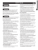
SAFETY RULES ASSEMBLY 2 • Tighten the spindle nut just enough to hold the grinding wheel firmly to the bench grinder. Do not overtighten, excessive clamping force can damage the grinding wheel. • Adjust distance between wheel and work rest to maintain 1/16 in. or less separation as the diameter of the wheel decreases with use. The value of separation used in the marking is to be the separation recommended by the manufacturer but shall not be more than 1/8 in.
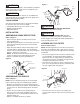
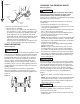
WARNING Eye Shield Wheel Guard Bolt To avoid injury, make sure all parts are assembled and adjusted properly before plugging the bench grinder into a power outlet and turning it ON. Carriage Bolt Eye shield mounting rod Do not operate bench grinder, until completely assembled. Do not operate this tool until you have completely read and understood this manual. ASSEMBLY Figure 3 WARNING Flat Washer Clamping Bracket TOOLS NEEDED You will need the following tools to assemble and adjust the machine.
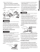
ASSEMBLY CHANGING THE GRINDING WHEEL Figure 5 Refer to Figure 7 WARNING Tool Rest Tool Rest Knob 4 Tool Rest Support Large Flat Washer • Repeat to assemble the other tool rest. • Adjust the tool rest assembly. • Loosen the tool rest support knob and slide the tool rest assembly in or out to maintain a distance of 1/8" (3.18 mm) or less between the grinding wheel and inside edge of the tool rest. When the tool rest is positioned correctly, tighten the locking knobs.
Figure 7 Outer Wheel Guard Optional Spacers needed when using optional accessories Eye Shield Grinding Wheel Outer Wheel Flange • The plug must be plugged into an outlet that is properly installed and grounded in accordance with all local codes and ordinances. • Check with a qualified electrician or service personnel if these instructions are not completely understood or if in doubt as to whether the tool is properly grounded. • Do not modify plug provided.
Extension Cord Length Wire Size…………….. A.W.G. Up to 25 ft…………… 16 gauge OPERATION NOTE: Using extension cords over 25 ft. long is not recommended. OPERATION 6 The following section is designed to give instructions on the basic operations of this bench grinder. However, it is in no way comprehensive of every grinder application. It is strongly recommended that you read books, trade magazines or get formal training to maximize the potential of your bench grinder and to minimize the risks.
GENERAL MAINTENANCE CAUTION REPLACE the grinding wheels if there is any damage at all. FAILURE to replace a damaged wheel can cause serious injury to the operator. WARNING Repairs to the bench grinder should be performed by trained personnel only. Unauthorized repairs or replacement with non-factory parts could cause serious injury to the operator and damage to the bench grinder.
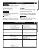
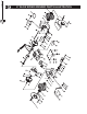
PARTS LIST 8 8 8" SLOW SPEED GRINDER PARTS ILLUSTRATION
Key Part No. Description No. 1 BGSS801001 Philips screw 2 BGSS801002 Cup head square neck bolt 3 BGSS801003 I type hex nut 4 BGSS801004 Flange 5 BGSS801005 Wheel 6 BGSS801006 Philips screw with spring washer 7 BGSS801007 Spark deflector 8 BGSS801008 Philips screw with flat wahser 9 BGSS801009 Eye shield 10 BGSS801010 Left eye shield support 11 BGSS801011 Flat washer 12 BGSS801012 Eye shield pressing plate assy.
WARRANTY 10 WARRANTY Thank you for investing in a POWERTEC power tool. This product has been designed and manufactured to meet high quality standards and is guaranteed for domestic use against defects in workmanship or material for a period of 12 months from the date of purchase. This guarantee does not affect your statutory rights. 10 SOUTHERN TECHNOLOGIES LLC.
NOTE
NOTE
NOTE