Model No. BS900 Owner’s Manual 9” BAND SAW QUESTION... 1•877•393•7121 Visit us on the web at www.southerntechllc.com You will need this manual for safety instructions, operating procedures, and warranty. Put it and the original sales invoice in a safe, dry place for future reference.
TABLE OF CONTENTS SECTION PRODUCTION SPECIFICATIONS PAGE PREPARATION 1 Depth of throat at 90° . . . . . . . . . . . . . . . . . . . . . . . . . . . 9” Maximum depth of cut at 90°. . . . . . . . . . . . . . . . . . . 3-5⁄8” Work Preparation Work Area Preparation Tool Should Be Maintained Know How to Use Tool Maximum depth of cut at 45°. . . . . . . . . . . . . . . . . . . . . . 2” Table Size. . . . . . . . . . . . . . . . . . . . . . . . . . . . 11¾ x 11¾” Table Tilt. . . . . . . . . . . . . .
SAFETY RULES WARNING For your own safety, read and understand all warnings and operating instructions before using any tool or equipment. WARNING Some dust created by operation of power tool contains chemicals known to the State of California to cause cancer, birth defects or other reproductive harm. To reduce your exposure to these chemicals, work in a well ventilated area and work with approved safety equipment.
ASSEMBLY 2 UNPACKAGING Refer to Figure 1. Figure 2 • Check for freight damage before opening the package. If freight damage is noticed, file claim with the carrier immediately. • Check to ensure all parts are present. Contact Customer Service Center immediately for missing parts. • This band saw comes mostly assembled. It requires some additional assembling, installation, and adjusment before use. • Locate the following parts before assembling: A. Mitre Gauge Assembly B. Table Assembly C.
GROUNDING INSTRUCTIONS A temporary 3-prong to 2-prong grounding adapter (see Figure 5) may be used to connect this plug to a matching 2-conductor receptacle as shown in figure 5. The temporary adapter should be used only until a properly grounded outlet can be installed by a qualified electrician. Figure 5 2-Prong Receptacle Grounded outlet Box Adapter WARNING Improper connection of equipment grounding conductor can result in the risk of electrical shock.
OPERATION 4 DESCRIPTION • This 9” band saw has welded steel frame and aluminum table. It is designed to cut woods, plastics, and nonferrous metals. The solid durable structure will withstand continuous heavy-duty workloads for many years to come. • This band saw is equipped with miter gauge for various precision operations. • The versatile adjustable table can be easily tilted to any angle between 0 and 45 degrees. • Simple and quick saw blade tension adjustment.
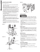
Figure 7 Tension Knob Blade Tension Lever Tracking Window Upper Guide Adjusting Knob Door Latch Tracking Knob Tensioning Spring Blade Guide Lock Knob • Properly adjust blade guide and support bearings before use. Figure 8 ADJUST BLADE TRACKING MECHANISM Refer to Figure 7 OPERATION • Turn the blade guide lock knob, located below the upper door latch, to release the upper blade guide assembly. • Turn the upper guide adjusting knob to lower the upper blade guide completely.
OPERATION 6 ADJUST BLADE GUIDES Figure 11 Refer to Figure 9 to 11 • Blade guides should not be in contact with the blade when not in operation. • Adjust the blade guides after the blade tracking and blade tension have been properly adjusted. • The blade guide supports the blade with bearings on the rear and guide pins on both sides. They all should be adjusted to be 0.016” inches away from the blade. and adjusted so that they are located just behind the set in the teeth.
OPERATION BEVEL CUTTING • Beveled cutting is to tilt saw table for the desired degree. • Loosen locking handle to unlock table. • Rotate knob to tilt table to desired position. • Lock table by tightening locking handle. 7 MAINTENANCE WARNING 7 LUBRICATION Turn the switch to the “OFF” position and disconnect the machine from power source before servicing or disassembling any components. • The shielded ball bearings are permanently lubricated and require no further lubrication.
8 TROUBLESHOOTING SYMPTOM POSSIBLE CAUSE(S) CORRECTIVE ACTION Motor will not start 1. Low voltage 2. Short circuit in line cord or plug 3. Short circuit in motor 4. Open circuit or loose connection in motor 5. Incorrect fuses or circuit breakers 6. Defective switch 7. Defective capacitor 1. Check power supply for proper voltage 2. Inspect line cord and plug for faulty insulation or shorted connection 3. Inspect connection on motor. 4. Inspect connection on motor 5.
9” BAND SAW PARTS ILLUSTRATION 9
9" BAND SAW PARTS LIST 10 Key No. 1 2 3 4 5 6 7 8 9 10 11 12 13 14 15 16 17 18 19 20 21 22 23 24 25 26 27 28 29 30 31 32 33 34 35 36 37 38 39 40 41 42 43 44 45 46 47 48 49 50 51 52 53 54 55 56 57 58 59 Part No.
9” BAND SAW PARTS LIST Key No. Part No. 119 120 121 122 123 124 125 126 127 128 129 130 BS900119 BS900120 BS900121 BS900122 BS900123 BS900124 BS900125 BS900126 BS900127 BS900128 BS900129 BS900130 Description Specification Rivet Flat Head Screw ø4x8L Pinion Set Screw M4x4L Bracket Washer ø6 Handle Hex Socket Head Screw M5xP0.8x10L Plug Blade Hexagonal Nut M6 Hex Head Screw M6x23L Qty 8 8 1 1 1 1 1 2 1 1 1 1 Key No. 131 132 133 134 135 136 137 138 139 140 141 Part No.
13 WARRANTY Thank you for investing in a POWERTEC power tool. These products have been designed and manufactured to meet high quality standards and are guaranteed for domestic use against defects in workmanship or material for a period of 12 months from the date of purchase. This guarantee does not affect your statutory rights. SOUTHERN TECHNOLOGIES LLC.
DISCLAIMER To the extent permitted by applicable law, all implied warranties, including warranties of MERCHANTABILITY or FITNESS FOR A PARTICULAR PURPOSE, are disclaimed. Any implied warranties, that cannot be disclaimed under state law are limited to one year from the date of purchase. Southern Technologies LLC. is not responsible for direct, indirect, incidental or consequential damages.
Southern Technologies, LLC 206 Terrace Drive Mundelein, Illinois 60060