Model 1000AR Regenerative Brushless DC Motor Control INSTALLATION AND OPERATION INSTRUCTION MANUAL JUNE, 2001
Model 1000AR Installation and Operation Manual PAGE 1 INTRODUCTION W HAT I S A G E N E S I S S E R I E S B R U S H L E S S D C D R I V E ? The GENESIS series of Brushless DC (BLDC) motor controls (drives) were developed to operate very large Brushless DC motors. Large BLDC motors were first made by POWERTEC Industrial Corporation in the late 1980’s. POWERTEC was acquired by Powertec in 1993. Small BLDC motors have been in use for many years.
Page 2 Model 1000AR Installation and Operation Manual S P E C I F I C ATI O N S Environmental ALTITUDE : Use above 3300 feet (1000 meters) requires de-rating. De-rate at 3% of full rating for each additional 1100 feet (330 meters). STORAGE TEMPERATURE : -40 °C to +65 °C (-40 °F to + 150 °F) AMBIENT TEMPERATURE : Chassis : Nema1 : Maximum air temperature of 55 °C (131 °F). Maximum air temperature of 40 °C (104 °F). RELATIVE HUMIDITY : Less than 95%, non-condensing.
Model 1000AR Installation and Operation Manual PAGE 3 RE GE NE RATIV E V E RS US NON-RE GE NE RATIV E OP E RATION Traditional AC induction motors and brush-type DC motors have windings on the rotor. They also have stationary windings on the frame that produce magnetic fields if we energize them. When the motor rotates, the windings move through the magnetic field. If we externally force the shaft to turn, this movement through magnetic fields produces a potential at the motor’s power terminals.
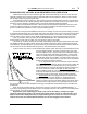
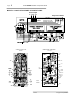
Page 4 Model 1000AR Installation and Operation Manual M O D E L 1 0 0 0 AR S TAN D AR D C O N N E C TI O N S Power Input L1 L2 L3 Output Terminals Input fuses Warning: Do Not Connect Input Power Leads to Output Terminals REGEN SPEED CONTROLLER 147-101 CURRENT CONTROLLER BOARD STAB GAIN MCL RCL POWERTEC JP1 MAX SPD JOG DIR/RL POWER DIR SEL JP3 GREEN DECEL ACCEL STALL HS3 RED RED BUS HS2 RED/GREEN RED ENABLE HS1 YELLOW COAST STOP PL TAC RED/GREEN RED OV/UV RED REGEN ENABLED
Model 1000AR Installation and Operation Manual PAGE 5 QUICK START Follow these steps to quickly set up and operate the Model 1000AR Brushless DC drive. If you are not sure of the procedure for any of the steps, consult the installation section (beginning on page 9). C O N N E C TI O N S 1. Connect the proper three-phase AC power from a suitably rated switching device to the input terminals L1, L2, and L3. Check the nameplate. The sequence of the phases is not important to the drive. 2.
Page 6 Model 1000AR Installation and Operation Manual R E F E R E N C E P AG E S Specifications.......................................................................................................................................... 2 Model 1000AR Standard Connections.................................................................................................... 4 Model 1000AR Dimensions Chart ........................................................................................................
Model 1000AR Installation and Operation Manual PAGE 7 TABLE OF CONTENTS INTRODUCTION ..................................................................................................................................................... 1 REGENERATIVE … OPERATION ................................................................................................................... 3 QUICK START .....................................................................................................................
Page 8 Model 1000AR Installation and Operation Manual 6/4/2001 © copyright 1997 by Powertec
Model 1000AR Installation and Operation Manual PAGE 9 INSTALLATION ® ® Underwriter’s Laboratories requires this notice for UL listed equipment. This Notice applies to POWERTEC Brushless DC Drive Model Number 1000AR. Do not use this device on a circuit capable of delivering more than 5000 RMS symmetrical Amperes at 500 VAC maximum voltage. M O TO R P R O TE C TI O N C O N S I D E R ATI O N S You are installing a GENESIS Series Brushless DC (BLDC) drive and motor.
Page 10 Model 1000AR Installation and Operation Manual M O D E L 1 0 0 0 AR D I M E N S I O N S C H AS S I S U N I TS Note: 10HP @ 230VAC, 10HP @ 380VAC, and 15HP @ 460VAC have the same dimensions, but they have separately mounted bus loaders 9.85" 250mm Ø 0.28" DIA 7.1mm TYP 4 places 9.13" 232mm 2.00" 51mm TYP 14.00" 356mm 18.00" 457mm R+ R- 8.35" 212mm 9.25" 235mm E N C L O S E D U N I TS Note: Units with separately mounted bus loaders come in a 34”H x 24”W x 18”D Nema1 Enclosure. 9.
Model 1000AR Installation and Operation Manual PAGE 11 HOW DO I … P H Y S I C AL L Y I N S TAL L TH E M O D E L 1 0 0 0 AR D R I V E ? Use of the Model 1000AR drive above 3300 ft (1000 meters) requires de-rating. If the drive is to be stored, store it in its original packaging in a dry environment. Storage temperature should be between -40°C and +65°C.
Page 12 Model 1000AR Installation and Operation Manual NOMINAL AC LINE VOLTAGE HORSEPOWER KILOWATTS ‡ 230 230 230 230 230 230 230 230 230 ½ ¾ 1 1.5 2 3 5 7.5 10 0.37 0.56 0.75 1.1 1.5 2.2 3.7 5.6 7.5 MAXIMUM CONTINUOUS AC LINE CURRENT 1.4 1.8 2.4 3.6 4.9 7.3 12.1 18.1 23.9 0.550 0.725 0.950 1.450 1.950 2.900 4.825 7.200 9.525 MAXIMUM HEAT OUTPUT IN WATTS 35 42 60 85 122 165 232 281 385 ‡ 380 380 380 380 380 380 380 1 1.5 2 3 5 7.5 10 0.75 1.1 1.5 2.2 3.7 5.6 7.5 1.5 2.2 2.9 4.4 7.3 10.9 14.
Model 1000AR Installation and Operation Manual PAGE 13 HOW DO I … CO NNE CT AC P O W E R T O T HE 1 0 0 0 AR DRI V E ? Standard Model 1000AR Brushless DC drives will not operate on single phase AC power. Model 1000AR drives require a three-phase main power source with a KVA rating at least equal to the HorsePower rating of the drive. Power is NOT returned to the power line during regeneration. .
Page 14 Model 1000AR Installation and Operation Manual M O D E L 1 0 0 0 AR F U S E B O AR D M o d e l 1 0 0 0 AR O u t p u t E l e c t r i c a l R a t i n g s NOMINAL AC LINE VOLTAGE HORSEPOWER KILOWATTS MAXIMUM CONTINUOUS MOTOR CURRENT MAXIMUM MOMENTARY MOTOR CURRENT NOMINAL HP CALIBRATE RESISTOR ‡ 230 230 230 230 230 230 230 230 230 ½ ¾ 1 1.5 2 3 5 7.5 10 0.37 0.56 0.75 1.1 1.5 2.2 3.7 5.6 7.5 2.2 3.4 4.7 7.0 8.5 12.8 22.8 31.1 41.5 3.3 5.1 7.0 10.5 12.7 19.2 34.2 46.6 61.1 68.1 K 45.
Model 1000AR Installation and Operation Manual PAGE 15 HOW DO I … CONNE CT THE MOTOR TO THE 1 0 0 0 AR DRIV E ? We ship every drive from the factory with A STANDARD CONNECTIONS card. Connect the motor lead marked T1 to the T1 terminal on the drive. Connect the T2 lead to T2 on the drive, and connect T3 to T3. Other connections to T1, T2, and T3 at the motor will vary with the motor. The motor will not operate if the power wires from motor to drive are not in the proper order.
Page 16 Model 1000AR Installation and Operation Manual RE G E NE RAT I V E RE S I S T O RS Regenerative motor controllers require a method of handling energy that is generated by the motor and returned to the drive. Traditionally, this has been handled by two methods: (1) using the power lines as a power sink by dumping excess energy back into the power source, and (2) dissipation as heat.
Model 1000AR Installation and Operation Manual PAGE 17 HOW DO I … CONNE CT THE RE GE NE RATIV E RE S I S TORS TO THE MODE L 1 0 0 0 AR? R+ R- CONTROL CIRCUIT INTERLOCK BUS LOADER RESISTOR(S) All but the largest Model 1000AR drives have the bus loader (149-201)built into the chassis. The bus loader mounts on the lower left-hand side panel and it plugs directly to the driver board. The power components for the bus loader are on the lower third of the chassis.
Page 18 Model 1000AR Installation and Operation Manual C O N TAC TO R S P E C I F I C ATI O N S If you want to operate an Output or DB Contactor directly from the Model 1000AR, you must choose a coil that draws less than 50 milliamps DC. The Output Contactor drawing on page 11 shows the connections for direct operation of the contactor (use the same connections for Dynamic Braking). The coil must be 48VDC and draw less than 50 ma DC (2.4 Watts).
Model 1000AR Installation and Operation Manual PAGE 19 HOW DO I … CONNE CT AN OUTP UT CONTACTOR? T2 You may use an output contactor with the Model 1000AR. You MUST interlock the contactor with the Emergency Stop. You WILL damage the drive if you do not interlock the contactor. T3 T1 GND M T1 Requirements for the Model 1000 series are: 1. The contactor must close its main power contacts BEFORE it enables the drive; 2. The contactor may only open its contacts AFTER disabling the drive.
Page 20 Model 1000AR Installation and Operation Manual M O D E L 1 0 0 0 AR C O N TR O L C O N N E C TI O N S MOTOR T H E R M AL EMERGENCY STOP R AM P S T O P STD: CONNECT FROM TB2-10 TO TB5-1** +24VDC ON TB2-11 STD: N/C PB FROM TB2-11 TO TB5-3** +24VDC ON TB2-12 STD: N/C PB FROM TB2-11 TO TB2-12 S T AR T / RUN +24VDC ON TB2-13 STD: N/O PB FROM TB2-12 TO TB2-13 RUN C O N T AC T TB2-7 AND TB2-8 ZERO SPEED OUTPUT: TB2-1 COMMON: TB2-16 -24VDC ON TB2-14 JOG STD: N/O PB FROM TB2-9 TO TB2-14 -24VDC O
Model 1000AR Installation and Operation Manual PAGE 21 HOW DO I … CONNE CT S TANDARD CONTROL CIRCUITS ? If you are using an output contactor or dynamic braking, go to page 19. The table on the opposite page lists the functions of the Model 1000AR. The table lists the connections and descriptions of the control circuits. Read the descriptions of the operations of these circuits very carefully. There are differences between analog and digital modes.
Page 22 Model 1000AR Installation and Operation Manual TE R M I N AL D E S C R I P TI O N S - M O D E L 1 0 0 0 AR TB1 Current Controller Board (141-108) 1 Dedicated Shields and Ground connection 2 HS1 position encoder 3 HS3 position encoder 4 HS2 position encoder 5 HS4 speed encoder 6 HS5 speed encoder 7 Encoder Common for encoder ONLY 8 Encoder +5 VDC for encoder ONLY 9 Isolated Common for terminals 10 and 11 10 Auto/Manual Selection +24 VDC for Digital Mode 11 External Frequency Input +24 VDC Square
Model 1000AR Installation and Operation Manual PAGE 23 The RUN relay contact at TB2 terminals 7 and 8 is a dry contact rated at 1 Amp (Resistive load) at 125VAC. You may use it in an external circuit as long as the voltage does not exceed 125 VAC (limitation of the terminal strip). You may use an auxiliary relay if you need more power, or if you need more contacts, as shown in the drawing at the left. You should use a 48VDC coil (highly recommended) since this reduces the burden on one supply.
Page 24 Model 1000AR Installation and Operation Manual P L C I N TE R F AC E SINKING CONNECTION PLC INPUT MODULE TB2 DRIVE +24VDC ZERO SPEED 10 +V 1 INPUT COM 16 SOURCING CONNECTION TB2 DRIVE +24VDC PLC INPUT MODULE +V 10 2Kohm MIN ZERO SPEED 1 INPUT 16 COM Most of the signals are +24 VDC or 48 VDC (positive and negative 24 VDC supplies for control), or +10 VDC for speed. You may also use computer generated frequency signals for speed in the DIGITAL mode.
Model 1000AR Installation and Operation Manual PAGE 25 HOW DO I … CO NNE CT AN ANALO G S P E E D RE F E RE NCE ? The analog speed reference for the Model 1000AR is 10 VDC to +10 VDC with the positive connection on TB2 terminal 5 and the common connection on TB2 terminal 16. Voltages less than -10 VDC become non-linear and voltages greater than 10 VDC become non-linear. The input impedance is about 100K.
Page 26 Model 1000AR Installation and Operation Manual D I G I TAL M O D E N O TE S Since the Brushless DC motor control system is inherently digital, the performance in the digital mode of operation far exceeds the performance in the analog mode. In the digital mode the control and motor respond to a frequency signal fed to the control from an external source. In the digital mode, we use the same digital control circuitry for the speed control as we do in the analog mode.
Model 1000AR Installation and Operation Manual PAGE 27 HOW DO I … C O N N E C T A D I G I T AL S P E E D R E F E R E N C E ? Apply +24VDC to TB1 terminal 10 (TB1-10) with respect to TB1-9 to operate the Model 1000 with a digital reference. Terminal 9 on TB1 is NOT the same as drive common. A jumper from TB2-10 will NOT switch to digital mode unless you connect TB1-9 to a drive common terminal (TB1-16). With +24VDC on TB1-10, a pulse train at TB111 (with respect to TB1-9) commands the motor movement.
Page 28 Model 1000AR Installation and Operation Manual AN AL O G V E R S U S D I G I TAL O P E R ATI O N The choice between ANALOG and DIGITAL operation comes down to performance. In ANALOG mode, a voltage sets the speed of the motor. Due to analog component tolerances, the best accuracy you can expect is on the order of +/- 1%. It is typically 0.1% or better. The biggest problem with Brushless DC is not the following of an analog source. It is the obtaining of a clean and stable analog source to follow.
Model 1000AR Installation and Operation Manual PAGE 29 HOW DO I … C O N N E C T A D I G I M AX ® ? ® The DIGIMAX is a crystal-based Speed or Ratio controller. It creates a train of pulses to command the movement of a motor when the drive is operating in digital speed mode. A suitable train of pulses applied at TB1 terminal 11 (with respect to TB1-9) of the Model 1000 commands the drive to turn the motor 3° for each pulse.
Page 30 Model 1000AR Installation and Operation Manual Power Input L1 L2 L3 Output Terminals Warning: Do Not Connect Input Power Leads to Output Terminals Input fuses Model 1000AR Standard Connections NOTICE: ANY POWER EQUIPMENT SWITCHING HIGH VOLTAGES AT HIGH FREQUENCIES EMITS RADIO FREQUENCY INTERFERENCE ( RFI ) AND ELECTROMAGNETIC INTERFERENCE ( EMI ). THE MOTOR LEADS MUST BE RUN IN METALLIC CONDUIT TO PREVENT INTERFERENCE WITH OTHER EQUIPMENT.
Model 1000AR Installation and Operation Manual PAGE I N S TAL L ATI O N C H E C K L I S T Is the Model 1000AR securely mounted in a vertical position (fuses up) [page 5]? Is there a clear path for airflow through the base heatsink and through the chassis [page 5]? Is the temperature of the air surrounding the drive within specifications [page 5]? Is the AC power source for the drive of the proper voltage, frequency, and capacity [page 7]? Is the motor securely mounted and aligned [motor manual]? Is the dr
Page 32 Model 1000AR Installation and Operation Manual BUS CONNECTIONS ARE ON THE CAPACITOR BOARD ON THE RIGHT SIDEWALL. BEHIND FRONT PANELS.
Model 1000AR Installation and Operation Manual CURRENT CONTROLLER BOARD PAGE 33 W H AT H AP P E N S W H E N I … AP P L Y P O W E R T O T HE MO DE L 1 0 0 0 AR ? When you apply the power to the Model 1000AR, the graph below demonstrates what happens to the drive’s bus voltage.
Page 34 Model 1000AR Installation and Operation Manual J UMP E RS STAB GAIN MCL RCL JP1 MAX SPD JOG SPD DIR/RL JUMPER 2Q OP DECEL ACCEL CURRENT LIMIT 2Q/4Q JUMPER RAMP STOP JUMPER FWD/REV JUMPER RAMP STOP P4 REGEN ESTO P RUN JOG ENABLED RUN CURRENT CONTROLLER BOARD 141-108 JP1 - “AF-N” Jumper - Used to decide whether or not the drive is permanently in the “DIGITAL” mode. This selection overrides the input at TB1 terminal 10.
Model 1000AR Installation and Operation Manual PAGE 35 W H AT H AP P E N S W H E N I … G I V E TH E S TAR T C O M M AN D TO TH E M O D E L 1 0 0 0 ? Before starting the Model 1000AR drive, turn the Current Limit pots fully counter-clockwise, and the speed reference command input, analog or digital, should be set to zero. E.
Page 36 Model 1000AR Installation and Operation Manual L E D I N D I C ATO R S CURRENT CONTROLLER BOARD 141-108 PWR Power BUS Bus Status HS1 Hall Sensor 1 HS2 Hall Sensor 2 HS3 Hall Sensor 3 TAC Hall Sensor 4 Hall Sensor 5 ENBL Enable STALL Stall Fault PL Power Loss OV/UV Overvoltage UnderVoltage IOC Instantaneous OverCurrent Phase Advance PHAD Turns ON GREEN as soon as power is applied to the drive. Turns OFF when power is removed from the drive.
Model 1000AR Installation and Operation Manual PAGE W H AT H AP P E N S W H E N I … G I V E TH E S P E E D C O M M AN D TO TH E M O D E L 1 0 0 0 AR ? Once the drive is in RUN mode, the application of the speed reference should cause the motor to turn. At this point: • the PWR and BUS LED’s on the Current Controller board should be GREEN; • one or two of the HS1, HS2, and HS3 LED’s should be on, • the ENABLE LED should be ON on both Speed Controller and Current Controller.
Page 38 Model 1000AR Installation and Operation Manual L E D I N D I C ATO R S SPEED CONTROLLER BOARD 141-107 RUN RUN mode CURRENT LIMIT Current Limit ENABLED Enable REGEN Regen Mode ESTP EStop Input JOG Jog Input HOLD Hold Input Turns ON GREEN when +24VDC is applied to TB2 terminal 13. Stays ON GREEN as long as +24VDC is applied to TB2-12 or TB2-13. Turns off when + 24VDC is removed from BOTH TB2-12 and TB2-13. Turns on GREEN when speed demand cannot be satisfied.
Model 1000AR Installation and Operation Manual PAGE 39 W H AT H AP P E N S W H E N I … S L O W D O W N O R O V E R H AU L TH E M O D E L 1 0 0 0 AR ? Since the Model 1000AR is a regenerative drive (see page 3), the motor does not coast when the speed reference is reduced. The deceleration ramp is enforced by removing energy from the motor. This is accomplished by treating the motor as a generator and applying a load to it.
Page 40 Model 1000AR Installation and Operation Manual AD J U S TM E N TS CCW = Counter-ClockWise position CW = ClockWise position MAX SPD Maximum Speed ANALOG MODE only. Not an absolute speed limit. Calibration to reference. At CCW, with 10VDC input, generates a VCO frequency of 1200 Hertz. At CW, with 10VDC input, generates VCO frequency of 10 Kilohertz. JOG SPD Jog Speed ANALOG MODE only. Sets speed during JOG mode. CCW is zero Jog Speed. CW is a jog speed of about 30% of full speed.
Model 1000AR Installation and Operation Manual PAGE 41 W H AT H AP P E N S W H E N I … M AK E AN AD J U S TM E N T O N TH E M O D E L 1 0 0 0 AR ? Once the motor is running, it may be necessary to make adjustments to produce the desired results. ACCEL time MAX speed Speed Pot to CCW ZERO speed START Speed Pot at CCW Speed Pot to CW DECEL time Speed Pot to Center STOP ACCEL time JOG speed JOG JOG ON OFF RAMP STOP The speed pot may be connected for bi-polar reference input.
42 Page Model 1000AR Installation and Operation Manual Rcharge L1 CONNECTIONS FOR 6 TRANSISTOR MODULE INDUCTOR 1 P CR1 HS BUSS FUSE 1 D2 2 BuP R3 CR1 3 BvP BwP C9 R+ TO P2 CURRENT CONTROLLER BRN VIO HIGH VOLTAGE CONNECTIONS POWER TRANSFORMER PRIMARY 380 OR 460 VAC T1 T2 T3 BwN BvN EwN YELLOW BLACK YELLOW RED BLACK ORANGE B2 E2 B5 E5 P3 W 6 EvN B1 E1 B4 E4 TO P3 CURRENT CONTROLLER L2 B3 E3 B6 E6 BASE DRIVER BOARD 141-105 P1 WH BRN POWER TRANSFORMER PRIMARY 230 VAC
Model 1000AR Installation and Operation Manual PAGE 43 T RO UBLE S HO O T I NG T HE MO DE L 1 0 0 0 AR DRI V E Troubleshooting of the Model 1000AR drive should only be attempted by personnel experienced in working on high-voltage, high power equipment. Equipment Necessary for Troubleshooting : 1. Safety Glasses 2. A Volt-Ohm-Milliammeter, preferably digital, with: • • • • • • .
Page 44 Model 1000AR Installation and Operation Manual TR AN S I S TO R M O D U L E S TATI C TE S T Equipment needed: A Digital Multi-Meter (DMM)with a diode scale is preferred. You should have a RED lead in the positive (+) input and a BLACK lead in the negative (-) input. Preparation: Different meters give different readings on diode tests. KNOW YOUR METER !! Some meters read backwards due to battery polarity.
Model 1000AR Installation and Operation Manual PAGE POWERTEC Model 1000AR Drive Start Up and Troubleshooting Chart NOTE: This chart assumes standard control connections and no options installed which affect speed control. CC = Current Controller board. SC = Speed Controller board. Page 1 START Check for grounds, then turn on power Is PWR LED ON ? Yes No Turn Power Off Remove Fuse. Unplug P2 on CC. Replace Fuse Start Over.
Page 46 Model 1000AR Installation and Operation Manual D I O D E B R I D G E TE S T Equipment : A Digital Multi-Meter (DMM)with a diode scale is preferred. You should have a RED lead in the positive (+) input and a BLACK lead in the negative (-) input. Preparation: Different meters give different readings on diode tests. KNOW YOUR METER !! Some meters read backwards due to battery polarity. Test YOUR meter on a known good diode bridge before performing tests so that you know how your meter will act.
Model 1000AR Installation and Operation Manual PAGE POWERTEC Model 1000AR Drive Start Up and Troubleshooting Chart Page 2 Wait up to 30 seconds for BUS LED to change from RED to GREEN NOTE: This chart assumes standard control connections and no options installed which affect speed control. CC = Current Controller board.
Page 48 Model 1000AR Installation and Operation Manual MOTOR ENCODER CONNECTIONS IN MOTOR TERMINAL BOX MOTOR ENCODER LAYOUT 6/4/2001 © copyright 1997 by Powertec
Model 1000AR Installation and Operation Manual PAGE POWERTEC Model 1000AR Drive Start Up and Troubleshooting Chart Page 3 NOTE: This chart assumes standard control connections and no options installed which affect speed control. CC = Current Controller board. Yes Is HS1 LED ON ? From Page 2 You can see the rotation of these three LED's by turning the motor by hand. There should always be one or two on at a time never all three on and never all three off.
Page 50 Model 1000AR Installation and Operation Manual I O C TE S TS : An Instantaneous Over Current (IOC) fault is a serious matter. An IOC fault is indicated when the drive has detected a potentially damaging amount of current going into the output transistor stage. Whenever possible, avoid trying to restart the drive after an IOC fault until the following tests have been performed: 1. 2. 3. 4. 5. 6. 7. 8. 9. Turn off power and wait for the main power capacitors to discharge.
Model 1000AR Installation and Operation Manual PAGE POWERTEC Model 1000AR Drive Start Up and Troubleshooting Chart Page 4 Press START Button and Release (See note above) From Page 3 Is RUN LED ON ? Is ENBL LED ON ? Yes No Press and HOLD START Button NOTE: This chart assumes standard control connections and no options installed which affect speed control. CC = Current Controller board.
Page 52 Model 1000AR Installation and Operation Manual BLOCK DIAGRAM - - SPEED CONTROLLER AND CURRENT CONTROLLER 6/4/2001 © copyright 1997 by Powertec
Model 1000AR Installation and Operation Manual PAGE POWERTEC Model 1000AR Drive Start Up and Troubleshooting Chart Page 5 Increase SPEED reference from 0% to 10%. If ILIMIT is at full CCW, turn it 25% CW. From Page 4 STOP. Turn off power. Disconnect TB1-7 and TB1-8 Is motor turning ? Is motor turning ? Yes No No Measure voltages at TB1-5 and TB1-6. TB1-7 is common. They switch between 0VDC and 8VDC as the motor turns.
Page 54 Model 1000AR Installation and Operation Manual DRIV E R BOARD LAYOUT AND CONNE CTIONS DRIV E R BOARD LE D’S The base driver board LED’s turn on when current is being supplied to the bases of the output power transistors. For output transistor numbering, see the Simplified Power Schematic drawing on page 32.
Model 1000AR Installation and Operation Manual PAGE POWERTEC Model 1000AR Drive Start Up and Troubleshooting Chart From Page 5 Page 6 Increase SPEED reference from 10% to 50%. If CURREN T LIMIT is turned down, turn it up to 50% CW. Correct Speed Reference Disconnect load from the motor and start over NOTE: This chart assumes standard control connections and no options installed which affect speed control. CC = Current Controller board. 50% speed refers to 1/2 of the max speed of the motor.
Page 56 Model 1000AR Installation and Operation Manual 6/4/2001 © copyright 1997 by Powertec