
Installation Guide
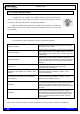
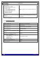
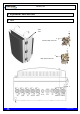
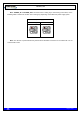
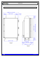
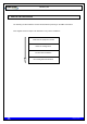
Table Of Contents
- 1. INTRODUCTION
- 2. UNPACKING AND CHECKING
- 3. PREVIOUS CONSIDERATIONS
- 4. INFORMATION ON SAFETY AND ELECTROMAGNETIC COMPATIBILITY
- 4.1 GENERAL CONSIDERATIONS ABOUT SAFETY
- 4.2 OPERATION AND EXPOSURE TO RF ENERGY
- 4.3 IMPORTANT SAFETY NOTES ABOUT THE ANTENNA
- 4.4 ELECTROMAGNETIC COMPATIBILITY REGULATORY INFORMATION (FCC AND ISED)
- 4.5 UL / SAFETY CERTIFICATIONS
- 4.6 EMC, SAFETY AND RF EXPOSURE STANDARDS
- 4.7 MECHANICAL AND ENVIRONMENTAL STANDARDS
- 5. EQUIPMENT DESCRIPTION
- 6. INSTALLATION GUIDE
- 6.1 NECESSARY EQUIPMENT
- 6.2 BASIC PRE-CONFIGURATION
- 6.3 INSTALLATION
- 6.3.1 MAST/POLE INSTALLATION
- 6.3.2 WALL INSTALLATION
- 6.3.3 PBS ACCESSORY INSTALLATION
- 6.3.4 ANTI-VANDAL KIT INSTALLATION
- 6.3.5 REQUIREMENTS TO CONSIDER DURING THE ANTENNA INSTALLATION
- 6.3.6 CONNECTIONS
- 6.3.6.1 SUPPORTED CONFIGURATIONS
- 6.3.6.1.1 ONE MBS UNIT WITH DIVERSITY 1 IN RECEPTION
- 6.3.6.1.2 ONE MBS UNIT WITH DIVERSITY 2 IN RECEPTION
- 6.3.6.1.3 TWO MBS UNIT (SAME SUBBAND) WITH DIVERSITY 1 OR 2 IN RECEPTION
- 6.3.6.1.4 TWO MBS UNITS (DIFFERENT SUBBANDS) WITH DIVERSITY 1 IN RECEPTION
- 6.3.6.1.5 TWO MBS UNITS (DIFFERENT SUBBANDS) WITH DIVERSITY 2 IN RECEPTION
- 6.3.6.2 CONNECTION OF THE EXTERNAL POWER SUPPLY
- 6.3.6.3 ANTENNA CONNECTION
- 6.3.6.4 EXTERNAL ETHERNET CONNECTION
- 6.3.6.1 SUPPORTED CONFIGURATIONS
- 6.3.7 CONNECTING / DISCONNECTING THE MBS AC MAINS SUPPLY
- 6.3.8 CONNECTING / DISCONNECTING THE MBS FROM THE DC SUPPLY
- 7. START UP/CONFIGURATION/VERIFICATION
- 8. INCIDENTS

TETRA MBS UNIT. INSTALLATION GUIDE
F067646PT_2801
Page 17 of 62
en
Note: POWER_IN and POWER_OUT connectors have a coding key to avoid wrong connections; on the
following table is showed the location of this coding key depending on the MBS Unit power supply option.
External view of power supply panel connector
AC Power Supply
DC Power Supply
Note: The amount of power delivered by both PoE and PoE/ETH connectors to the radio links can not
exceed 35 W in total.