
Installation Guide
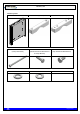
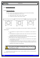
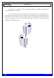
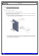
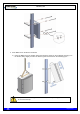
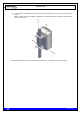
Table Of Contents
- 1. INTRODUCTION
- 2. UNPACKING AND CHECKING
- 3. PREVIOUS CONSIDERATIONS
- 4. INFORMATION ON SAFETY AND ELECTROMAGNETIC COMPATIBILITY
- 4.1 GENERAL CONSIDERATIONS ABOUT SAFETY
- 4.2 OPERATION AND EXPOSURE TO RF ENERGY
- 4.3 IMPORTANT SAFETY NOTES ABOUT THE ANTENNA
- 4.4 ELECTROMAGNETIC COMPATIBILITY REGULATORY INFORMATION (FCC AND ISED)
- 4.5 UL / SAFETY CERTIFICATIONS
- 4.6 EMC, SAFETY AND RF EXPOSURE STANDARDS
- 4.7 MECHANICAL AND ENVIRONMENTAL STANDARDS
- 5. EQUIPMENT DESCRIPTION
- 6. INSTALLATION GUIDE
- 6.1 NECESSARY EQUIPMENT
- 6.2 BASIC PRE-CONFIGURATION
- 6.3 INSTALLATION
- 6.3.1 MAST/POLE INSTALLATION
- 6.3.2 WALL INSTALLATION
- 6.3.3 PBS ACCESSORY INSTALLATION
- 6.3.4 ANTI-VANDAL KIT INSTALLATION
- 6.3.5 REQUIREMENTS TO CONSIDER DURING THE ANTENNA INSTALLATION
- 6.3.6 CONNECTIONS
- 6.3.6.1 SUPPORTED CONFIGURATIONS
- 6.3.6.1.1 ONE MBS UNIT WITH DIVERSITY 1 IN RECEPTION
- 6.3.6.1.2 ONE MBS UNIT WITH DIVERSITY 2 IN RECEPTION
- 6.3.6.1.3 TWO MBS UNIT (SAME SUBBAND) WITH DIVERSITY 1 OR 2 IN RECEPTION
- 6.3.6.1.4 TWO MBS UNITS (DIFFERENT SUBBANDS) WITH DIVERSITY 1 IN RECEPTION
- 6.3.6.1.5 TWO MBS UNITS (DIFFERENT SUBBANDS) WITH DIVERSITY 2 IN RECEPTION
- 6.3.6.2 CONNECTION OF THE EXTERNAL POWER SUPPLY
- 6.3.6.3 ANTENNA CONNECTION
- 6.3.6.4 EXTERNAL ETHERNET CONNECTION
- 6.3.6.1 SUPPORTED CONFIGURATIONS
- 6.3.7 CONNECTING / DISCONNECTING THE MBS AC MAINS SUPPLY
- 6.3.8 CONNECTING / DISCONNECTING THE MBS FROM THE DC SUPPLY
- 7. START UP/CONFIGURATION/VERIFICATION
- 8. INCIDENTS

TETRA MBS UNIT. INSTALLATION GUIDE
F067646PT_2801
Page 26 of 62
en
6.3.1 MAST/POLE INSTALLATION
6.3.1.1 MAST/POLE SELECTION
The types of section of the mast/pole where the MBS Unit can be mounted are the followings:
Circular section: Diameter from 1.18 in to 5.12 in.
Square section: From 1.18 in x 1.18 in to 3.35 in x 3.35 in.
L section: From 1.18 in x 1.18 in to 4.33 in x 4.33 in.
In the choice of the mast/pole where the MBS Unit is being installed the following recommendations
must be followed:
The mast/pole has to support the loads due to the installation of some elements on
them.
The mast/pole has to support the loads due to the action of the wind, snow as well as its
own weight, because these are going to induce its flexion.
o The mast/pole must have the enough inertia both lateral and frontal in order that the actions
of different loads do not induce permanent deformations on it.
The manufacturer of the mast/pole must evaluate the structural factor of the mast/pole
correctly depending on its type.
It is necessary to take into account both the height where the MBS Unit is installed and
its weight/dimensions (See section “MBS Unit” in chapter (F067326PT) “SBS Technical
Description” in the Standard Technical Manual).
It is recommended to choose a lattice mast/pole in case of this one has a high height
and it is going to be submitted to important flexion efforts. In any case, it is
responsibility of the manufacturer of the mast/pole to determine if the resistant
section of mast/pole is suitable.
The brackets should be installed tight enough to support the MBS Unit without causing deformation
of the mast/pole or areas of corrosion.