
Installation Guide
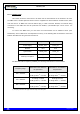
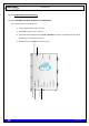

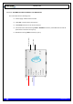
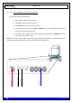
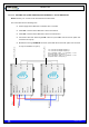
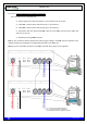
Table Of Contents
- 1. INTRODUCTION
- 2. UNPACKING AND CHECKING
- 3. PREVIOUS CONSIDERATIONS
- 4. INFORMATION ON SAFETY AND ELECTROMAGNETIC COMPATIBILITY
- 4.1 GENERAL CONSIDERATIONS ABOUT SAFETY
- 4.2 OPERATION AND EXPOSURE TO RF ENERGY
- 4.3 IMPORTANT SAFETY NOTES ABOUT THE ANTENNA
- 4.4 ELECTROMAGNETIC COMPATIBILITY REGULATORY INFORMATION (FCC AND ISED)
- 4.5 UL / SAFETY CERTIFICATIONS
- 4.6 EMC, SAFETY AND RF EXPOSURE STANDARDS
- 4.7 MECHANICAL AND ENVIRONMENTAL STANDARDS
- 5. EQUIPMENT DESCRIPTION
- 6. INSTALLATION GUIDE
- 6.1 NECESSARY EQUIPMENT
- 6.2 BASIC PRE-CONFIGURATION
- 6.3 INSTALLATION
- 6.3.1 MAST/POLE INSTALLATION
- 6.3.2 WALL INSTALLATION
- 6.3.3 PBS ACCESSORY INSTALLATION
- 6.3.4 ANTI-VANDAL KIT INSTALLATION
- 6.3.5 REQUIREMENTS TO CONSIDER DURING THE ANTENNA INSTALLATION
- 6.3.6 CONNECTIONS
- 6.3.6.1 SUPPORTED CONFIGURATIONS
- 6.3.6.1.1 ONE MBS UNIT WITH DIVERSITY 1 IN RECEPTION
- 6.3.6.1.2 ONE MBS UNIT WITH DIVERSITY 2 IN RECEPTION
- 6.3.6.1.3 TWO MBS UNIT (SAME SUBBAND) WITH DIVERSITY 1 OR 2 IN RECEPTION
- 6.3.6.1.4 TWO MBS UNITS (DIFFERENT SUBBANDS) WITH DIVERSITY 1 IN RECEPTION
- 6.3.6.1.5 TWO MBS UNITS (DIFFERENT SUBBANDS) WITH DIVERSITY 2 IN RECEPTION
- 6.3.6.2 CONNECTION OF THE EXTERNAL POWER SUPPLY
- 6.3.6.3 ANTENNA CONNECTION
- 6.3.6.4 EXTERNAL ETHERNET CONNECTION
- 6.3.6.1 SUPPORTED CONFIGURATIONS
- 6.3.7 CONNECTING / DISCONNECTING THE MBS AC MAINS SUPPLY
- 6.3.8 CONNECTING / DISCONNECTING THE MBS FROM THE DC SUPPLY
- 7. START UP/CONFIGURATION/VERIFICATION
- 8. INCIDENTS

TETRA MBS UNIT. INSTALLATION GUIDE
F067646PT_2801
Page 48 of 62
en
6.3.6.1.3.1 CONFIGURATION WITH PBS ACCESSORY
NOTE: Diversity 1 or 2 mode can be selected from the NMS client.
The connections are the following ones:
Power supply for the PBS Accessories 1 and 2: 220/110 VAC or 24 VDC.
From ANT connector of the PBS Accessory 1 to the first antenna.
From ANT connector of the PBS Accessory 2 to the second antenna.
Connection with radio link through PoE connector.
Note 1: The connection with the NMS Server-Client Rugged Laptop in the PoE connector depends of the
network topology and just applies in Isolated Operation Mode of the MBS Unit.
Note 2: The use of the PBS accessory for two MBS Units with SNI IP option is not supported.
PBS #1
Power Input
Ante
nna 1 (Tx
F1
/Rx1)
Power Input
Radio Link 2
Radio Link 1
Ante
nna 2(TX
F2
/Rx1)
TX
F1
: Transmission Output Frequency 1
TX
F2
: Transmission Output Frequency 2
RX1: Reception Chain 1 of Frequency 1 and
Reception Chain 2 of Frequency 2
RX2: Reception Chain 2 of Frequency 1 and
Reception Chain 1 of Frequency 2