
Installation Guide
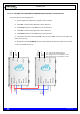
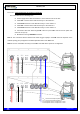
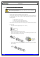
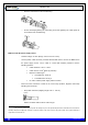
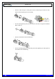
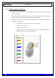


Table Of Contents
- 1. INTRODUCTION
- 2. UNPACKING AND CHECKING
- 3. PREVIOUS CONSIDERATIONS
- 4. INFORMATION ON SAFETY AND ELECTROMAGNETIC COMPATIBILITY
- 4.1 GENERAL CONSIDERATIONS ABOUT SAFETY
- 4.2 OPERATION AND EXPOSURE TO RF ENERGY
- 4.3 IMPORTANT SAFETY NOTES ABOUT THE ANTENNA
- 4.4 ELECTROMAGNETIC COMPATIBILITY REGULATORY INFORMATION (FCC AND ISED)
- 4.5 UL / SAFETY CERTIFICATIONS
- 4.6 EMC, SAFETY AND RF EXPOSURE STANDARDS
- 4.7 MECHANICAL AND ENVIRONMENTAL STANDARDS
- 5. EQUIPMENT DESCRIPTION
- 6. INSTALLATION GUIDE
- 6.1 NECESSARY EQUIPMENT
- 6.2 BASIC PRE-CONFIGURATION
- 6.3 INSTALLATION
- 6.3.1 MAST/POLE INSTALLATION
- 6.3.2 WALL INSTALLATION
- 6.3.3 PBS ACCESSORY INSTALLATION
- 6.3.4 ANTI-VANDAL KIT INSTALLATION
- 6.3.5 REQUIREMENTS TO CONSIDER DURING THE ANTENNA INSTALLATION
- 6.3.6 CONNECTIONS
- 6.3.6.1 SUPPORTED CONFIGURATIONS
- 6.3.6.1.1 ONE MBS UNIT WITH DIVERSITY 1 IN RECEPTION
- 6.3.6.1.2 ONE MBS UNIT WITH DIVERSITY 2 IN RECEPTION
- 6.3.6.1.3 TWO MBS UNIT (SAME SUBBAND) WITH DIVERSITY 1 OR 2 IN RECEPTION
- 6.3.6.1.4 TWO MBS UNITS (DIFFERENT SUBBANDS) WITH DIVERSITY 1 IN RECEPTION
- 6.3.6.1.5 TWO MBS UNITS (DIFFERENT SUBBANDS) WITH DIVERSITY 2 IN RECEPTION
- 6.3.6.2 CONNECTION OF THE EXTERNAL POWER SUPPLY
- 6.3.6.3 ANTENNA CONNECTION
- 6.3.6.4 EXTERNAL ETHERNET CONNECTION
- 6.3.6.1 SUPPORTED CONFIGURATIONS
- 6.3.7 CONNECTING / DISCONNECTING THE MBS AC MAINS SUPPLY
- 6.3.8 CONNECTING / DISCONNECTING THE MBS FROM THE DC SUPPLY
- 7. START UP/CONFIGURATION/VERIFICATION
- 8. INCIDENTS

TETRA MBS UNIT. INSTALLATION GUIDE
F067646PT_2801
Page 53 of 62
en
6.3.6.2 CONNECTION OF THE EXTERNAL POWER SUPPLY
Check that the power supply source and/or the battery to be used are adapted to the
type of MBS Unit (AC/DC) and meets the voltage and current requirements
necessary to supply the equipment.
MBS Unit with AC power supply source:
- Nominal voltage: 110/220 VAC (Range: from 94 to 264 VAC).
- Use the power cable connector provided with the MBS Unit to connect the MBS Unit to
the power supply source. Use a cable of 3 wires; with weather protection; with the
following features:
Cable diameter: 0.24 in - 0.47 in.
Cable section: 2.5 mm
2
(AWG 13) (0.6/1KV)
UL VW-1 certified power supply cable is needed.
- Ensure that the connection is made in the correct way (Line, Neutral and Earth) following
the next steps:
o Strip cable and wires (stripping length 0.31 in - 0.35 in).
NOTE: The earth cable must be 0.08 in longer.
o Push the cable through the cable gland and the hood/housing and insert the wires
into the insert respecting the correct polarity.
o Fix each wire tightening each pin from the front side with a hexagonal screwdriver
(Allen number 2).
8-9 mm
Neutral (N)
Line (L)
Earth (PE)