
Installation Guide
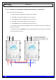
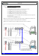
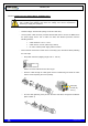
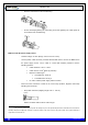
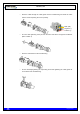


Table Of Contents
- 1. INTRODUCTION
- 2. UNPACKING AND CHECKING
- 3. PREVIOUS CONSIDERATIONS
- 4. INFORMATION ON SAFETY AND ELECTROMAGNETIC COMPATIBILITY
- 4.1 GENERAL CONSIDERATIONS ABOUT SAFETY
- 4.2 OPERATION AND EXPOSURE TO RF ENERGY
- 4.3 IMPORTANT SAFETY NOTES ABOUT THE ANTENNA
- 4.4 ELECTROMAGNETIC COMPATIBILITY REGULATORY INFORMATION (FCC AND ISED)
- 4.5 UL / SAFETY CERTIFICATIONS
- 4.6 EMC, SAFETY AND RF EXPOSURE STANDARDS
- 4.7 MECHANICAL AND ENVIRONMENTAL STANDARDS
- 5. EQUIPMENT DESCRIPTION
- 6. INSTALLATION GUIDE
- 6.1 NECESSARY EQUIPMENT
- 6.2 BASIC PRE-CONFIGURATION
- 6.3 INSTALLATION
- 6.3.1 MAST/POLE INSTALLATION
- 6.3.2 WALL INSTALLATION
- 6.3.3 PBS ACCESSORY INSTALLATION
- 6.3.4 ANTI-VANDAL KIT INSTALLATION
- 6.3.5 REQUIREMENTS TO CONSIDER DURING THE ANTENNA INSTALLATION
- 6.3.6 CONNECTIONS
- 6.3.6.1 SUPPORTED CONFIGURATIONS
- 6.3.6.1.1 ONE MBS UNIT WITH DIVERSITY 1 IN RECEPTION
- 6.3.6.1.2 ONE MBS UNIT WITH DIVERSITY 2 IN RECEPTION
- 6.3.6.1.3 TWO MBS UNIT (SAME SUBBAND) WITH DIVERSITY 1 OR 2 IN RECEPTION
- 6.3.6.1.4 TWO MBS UNITS (DIFFERENT SUBBANDS) WITH DIVERSITY 1 IN RECEPTION
- 6.3.6.1.5 TWO MBS UNITS (DIFFERENT SUBBANDS) WITH DIVERSITY 2 IN RECEPTION
- 6.3.6.2 CONNECTION OF THE EXTERNAL POWER SUPPLY
- 6.3.6.3 ANTENNA CONNECTION
- 6.3.6.4 EXTERNAL ETHERNET CONNECTION
- 6.3.6.1 SUPPORTED CONFIGURATIONS
- 6.3.7 CONNECTING / DISCONNECTING THE MBS AC MAINS SUPPLY
- 6.3.8 CONNECTING / DISCONNECTING THE MBS FROM THE DC SUPPLY
- 7. START UP/CONFIGURATION/VERIFICATION
- 8. INCIDENTS

TETRA MBS UNIT. INSTALLATION GUIDE
F067646PT_2801
Page 56 of 62
en
In both cases:
The power supply cable to the MBS Unit must be provided by the installer with the proper
power supply connector adapted for the connection to the electrical network or to a 24 VDC
source.
Ensure that the earth connection is made before equipment’s start-up. The MBS Unit has an
earth connector; this connector will connect to the earth protection of the installation, which
is different to the earth protection of the lightning rod.
Make this connection with a cable of, at least, 25 mm
2
(AWG 3) section
NEVER use a gas or electricity conduit as an earth.
6.3.6.3 ANTENNA CONNECTION
With every MBS Unit, a RF super-flexible wire, N-Male – N-Male, is supplied to connect the
ANT connector of the MBS Unit with the RF wire of the antenna.
Note: In case of installation a MBS Unit with diversity 2, it is recommended to contact your
supplier and/or installer who will provide the additional RF super-flexible wire (Cod. 208931).
The RF assembly depends on the cable type used in the installation up to the antenna.
The RF cable must have a protection against water entry (vulcanizable tape).
Choose the most adaptable antenna for the installation. The antenna must have an
impedance of 50 ohms to the equipment transmission frequency. Install the antenna in
accordance with the manufacturer’s instructions.
Use a coaxial cable, avoiding as much as possible large cable lengths. Cable impedance is
50 ohms.
In installations with diversity, the greatest gain is achieved by placing the antennas on the
same horizontal plane with a minimum distance of 6.01 yd between them.
Measure the ROE of the installation. Never accept a ROE greater than 2