USER MANUAL On-Line UPS PowerWalker VFI 6000RT LCD PowerWalker VFI 6000P/RT LCD PowerWalker VFI 10000RT LCD PowerWalker VFI 10000P/RT LCD
Uninterruptible Power Supply System Contents 1. Introduction ............................................................................................. 1 2. Safety Warnings ...................................................................................... 4 2.1 Installation .......................................................................................... 4 2.2 Operation ............................................................................................ 5 2.
8. Troubleshooting .................................................................................... 52 8.1 Typical Alarms and Conditions ......................................................... 52 9. Communication ..................................................................................... 57 9.1 RS-232 and USB Communication Ports .......................................... 57 9.2 Network Management Card (Optional) ............................................ 59 9.3 UPS Management Software ....
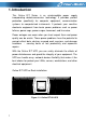
1. Introduction This Online R/T Series is an uninterruptible power supply incorporating double-conversion technology. It provides perfect protection specifically for computer equipment, communication systems to computerized instruments. It protects your sensitive electronic equipment from basic power problems such as power failures, power sags, power surges, brownout, and line noise. Power outages can occur when you least expect them and power quality can be erratic.
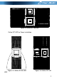
Figure 1-2: Online R/T 10K UPS Online R/T UPS as Tower installation.
Providing outstanding performance and reliability, the UPS’s unique benefits include: Online UPS design with pure sine wave output. True online double-conversion technology with high power density, utility frequency independence, and generator compatibility. Intelligent Battery Management technology that uses advanced battery management to increase battery service life, optimize recharge time. Selectable High Efficiency mode of operation.
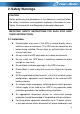
2. Safety Warnings CAUTION: Before performing the procedures in this document, read and follow the safety instructions and important regulatory information in your Safety, Environmental, and Regulatory Information document. IMPORTANT SAFETY INSTRUCTIONS FOR EACH STEP SAVE THESE INSTRRUCTIONS. 2.1 Installation Condensation may occur if the UPS is moved directly from a cold to a warm environment. The UPS must be absolutely dry before being installed.
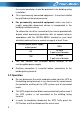
the neutral conductor should be provided in the building wiring installation. This is permanently connected equipment , it must be installed by qualified maintenance personnel. For permanently connected equipment: make sure that a readily accessible disconnect device is incorporated in the building installation wiring.
Ensure that no liquid or other foreign objects can enter the UPS. The UPS can be operated by any individual without previous experience. 2.3 Maintenance, servicing and faults The UPS operates with hazardous voltages. Maintenance should be carried out only by qualified maintenance personnel. Caution - risk of electric shock.
5) Do not open or destroy batteries. Effluent electrolyte can cause injury to the skin and eyes. It may be toxic. Please replace the fuse only with the same type and of the same amperage in order to avoid fire hazards. Do not dismantle the UPS, except the qualified maintenance personnel. 2.4 Transport Please transport the UPS only in the original packaging (to protect against shock and impact). 2.5 Storage The UPS must be stockpiled in the room where is ventilated and dry. 2.
Power-frequency Magnetic field.... :IEC/EN 61000-4-8 Level 3 Low Frequency Signals..................:IEC/EN 61000-2-2 Warning: This is a product for commercial and industrial application in the second environment-installation restrictions or additional measures may be needed to prevent disturbances.
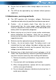
3. Installation This chapter explains: Equipment inspection Unpacking the cabinet Checking the Accessory UPS setup and installation Connecting the internal battery Connecting the EBM(Extended Battery Modules) Installation requirements 3.1 Inspecting the Equipment If any equipment has been damaged during shipment, keep the shipping cartons and packing materials for the carrier or place of purchase and file a claim for shipping damage.
Step 1: Open the outer carton and remove the accessories out of the carton (see Figure 3-1&3-2).
CAUTION: The cabinet is heavy. Lifting the cabinet out of the carton required two persons at least. Step 2: With one person on each side, carefully lift the cabinet out of the outer carton using the handles on the cardboard and set it on a flat, stable surface (see Figure 3-3&3-4). Place the cabinet in a protected area that has adequate airflow and is free of humidity, flammable gas, and corrosion.
Figure 3-4: Lifting the Cabinet out of 10K UPS carton Step 3: Discard or recycle the packaging in a responsible manner, or store it for future use. 3.3 UPS Rear Panel This section shows the rear panel of the Online R/T models.
10K model: Figure 3-6: Online R/T 10K Rear Panel 3.4 UPS Front Panel This section shows the front panel of the Online R/T UPS. The Online series have the same LCD panel and the same control button.
3.5 Rack mount Setup CAUTION: The cabinet is heavy, so: 1) Remove the battery tray from the UPS before lifting. 2) Lifting the cabinets into the rack requires a minimum of two people. CAUTION: Removing the batteries requiered precautions, which should be performed or supervised by personnel with knowledge of batteries . Keep unauthorized personnel away from batteries. CAUTION: If installing an EBM(Extended Battery Module), install the EBM directly below the UPS. 3.5.
3. Pull the battery tray out using the plastic tabs and then remove the battery tray. Figure 3-11: Removing the Battery Tray 4. Install the PDU’s ears to the UPS Figure 3-12. Install the PDU’s ears to the UPS 5. Select the proper holes in the rail for positioning the cabinet in the desired location in the rack. Locate the rails at the bottom of the 3U space allocated for the each UPS and EBM. 6. Install the sliding rails in the rack, then install the UPS in the sliding rail.
Figure 3-13. Install the sliding rails 7. For 10K---Install the battery pack and battery protection plate, then replace the front panel. Figure 3-14. Installing the Cabinet 8. For 6K---Replace the battery tray, and connect the internal battery connector, then replace the protection plate and the front panel. 9. If installing additional UPSs, repeat from Step 1 to Step 8 for each cabinet. 3.5.2 Installing the EBMs Note: A little of arcing may occur when connecting an EBM to the UPS.
To install EBMs: 6K Model: 1. Plug the EBM cable into the UPS battery connector Figure 3-15. Plug the EBM cable into the UPS battery connector 2. Replace UPS’s front panel and EBM’s front panel. Figure 3-16. Replace UPS’s front panel and EBM’s front panel.
CAUTION: Please connect the EBM to protective ground with 8 AWG wire for EBM model firstly. 10K Model: Figure 3-17. Plug the EBM cable into the UPS battery connector 3.6 Tower Setup Tower setup as below: Figure 3-18.
3.7 Installation of UPS with AC inputs CAUTION: Online 6K/10K series support that the UPS can have separate AC inputs. So before connecting wires of seperate AC inputs, you should confirm that their earthing systems are identical. Otherwise, a transformer is necessary. UPS with common Normal and Bypass AC inputs UPS with separate Normal and Bypass AC inputs Earthing systems are identical: Earthing systems are separate: Three different installations can be choosen: 1) Transformer in the Normal AC input.
2) Transformer in the Bypass AC input.
4.
4.1 Access to terminal block Access to terminal block: remove the 2 screws of the terminal block cover Figure 4-1. PDU of 6K/10K 4.
Figure 4-2. Common input sources connection 4.3 Separate input sources connection CAUTION: This type of connection must be carried out by qualified electrical personnel. CAUTION: Always connect the earthing wire first. Figure 4-3.
4.4 Frequency converter connection Figure 4-4. Frequency converter connection 4.5 UPS Initial Startup To start up the UPS: Verify that the total equipment ratings do not exceed the UPS capacity to prevent an overload alarm. 1. Verify that the internal batterties are connected. 2. If optional EBMs are installed, verify that the EBMs are connected to the UPS. 3. Set the upstream circuit breaker (not included) to the “I” position (ON). The UPS display panel illuminates and shows a status of “Welcome” 4.
7. Verify that the UPS is operating normally and any load is powered. 8. If optional EBMs are installed, see “Configuring the UPS for EBMs” to set the number of installed EBMs. 9. To change any other factory-set defaults, see “Operation” Online series recommends setting the date and time. At initial startup, the UPS sets system frequency according to input line frequency (input frequency auto-sensing is enabled by default).
2) Users need to use a specialty 15-pin communication cable for this system, which should have 15 cores, corresponding stitches and shield, as the UPS parallel cable. The length of the parallel cable is appropriate to be less than 3 m. 3) Strictly follow the chapter of 4, the wiring requirement of single UPS to perform the wiring of each UPS. 4) Independent battery packs for each UPS.
Figure 4-5.
Figure 4-5.
6) Turn on the input breakers for the two parallel UPS. 7) Pressing button continuously for more than 1 second for one UPS of the system, then the system will start to turn on and enter line mode. Regulate the output voltage of the each UPS separately, and check if the output voltage difference between the two ups is less than 0.5V. If the difference is more than 0.5V, the UPS need to be regulated. 8) 9) If the difference output voltage is less than 0.
4) 5) 6) 7) 8) Set the main maintenance switch or static switch from “UPS” to “BPS”, then switch off the main output breaker and the input breaker and mains breaker, then the UPS will shut down. Connect the cable and wire of the added UPS according to the Figure.4-5.a and Figure.4-5.b Switch on the input breakers and mains breaker, and make sure that every UPS work in bypass mode. Switch on the O/P breakers and main O/P breaker,transfer the main maintenance switch or static switch from “BPS” to “UPS”.
5. Operation 5.1 Display Panel The UPS has a four-button graphical LCD with dual color backlight. Standard back-light is used to light up the display with white text and a blue background. When the UPS has a critical alarm, the backlight changes the text to dark amber and the background to red. See Figure below Figure 5-1.
Enter main menu Exit main menu Scroll up Scroll down Enter next menu tree Select one menu option Confirm the present setting When displaying default UPS status summary screen, press this button for >1s to enter the main menu tree Press this button for >1s to exit the present menu to default system status display menu without executing a command or changing a setting Press this button for >100ms&<1s to scroll up the menu option Press this button for >100ms&<1s to scroll down the menu option Press this b
After powering on, the LCD will display Welcome logo for several seconds and then enter to the default page which shows the UPS status summary. The display automatically returns to the default UPS status summary screen when no button has been pressed within 15 minutes.
Table 5-3 Status Summary Screens Status Summary Screen Description Normal mode: The UPS is operating in Normal mode from utility power. Fig 5-3 Battery mode: When the UPS is running in battery mode, the buzzer beeps once every 4 seconds. Fig 5-4 Bypass with output: Fig 5-5 The UPS does not have the backup function when it is in bypass mode. The power used by the load is supplied from the utility power via internal filter. The UPS will beep once every 2 minutes in bypass mode.
Fig 5-8 software (Winpower, etc.). 2) It is attention that the transfer time of UPS output from HE mode to battery mode is about 10ms. But it is still too long for some sensitive load. Converter mode In converter mode, the UPS would free run with fixed output frequency (50Hz or 60Hz). Once the mains is loss or abnormal, the UPS would transfer to battery mode and the load is supplied continuously. 1) The function could be enabled through the LCD setting or the software (Winpower, etc.).
Overload: Fig 5-11 When the UPS is overload, the alarm will beep twice every second. Some unnecessary loads should be get rid of one by one to decrease the loads connected to the UPS. Battery Test UPS is executing a battery test Fig 5-12 Battery fail: Fig 5-13 if the battery status detected is “bad battery detected” or “battery disconnected”, the symbol of battery failure would be shown and UPS would alarm. 5.
4) A few seconds later, the UPS turns into Line mode. If the utility power is abnormal, the UPS will transfer to Battery mode without output interruption of the UPS. 5.3.2 Turning on UPS without utility 1) Check all the connection is correct. 2) Pressing button continuously for more than 100ms, the UPS would be powered on. At this time the fan begins to rotate, LCD will show the “WELCOME” logo. Then LCD will show the default UPS status summary screen after UPS finishing self-test.
5.4 LCD operation Except the default UPS status summary screen, the user could get more useful information about UPS current status, detailed various measurements, previous event records which ever occurred, UPS own identification, and could change the settings to fit the user own requirements, optimize the function of UPS. 5.4.1 The main menu In the default UPS status summary screen, when pressing or <1s, the detailed information about alarm, the system status, battery would be shown.
Figure.
5.4.2 The UPS status menu By pressing on the menu of “UPS status”, the display would enter the next UPS status menu tree. The content of UPS status menu tree is same as the default UPS status summary menu. By pressing tree. >1s, the display would return the last main menu The detail information about “UPS status”, please see Fig5-14 5.4.3 The event log menu By pressing on the menu of “Event log”, the display would enter the next event menu tree.
Figure. 5-15 Event menu tree 5.4.4 The measurement menu By pressing on the menu of “Measurement”, the display would enter the next measurement menu tree. A lot of detailed useful information could be checked here, Ex. the output voltage and frequency, the output current, the load capacity, the input voltage and frequency, etc. By pressing >1s, the display would return the last main menu tree.
Figure. 5-16 Measurement menu tree 5.4.5 The control menu By pressing on the menu of “Control”, the display would enter the next control menu tree. 1) Start Battery Test: this is one command that control the UPS to do the battery test. 2) Clear EPO status: once EPO status is enabled, the UPS output would be cut off. To recover to normal status, first EPO connector should be closed, and enter this menu to clear EPO status, then UPS would stop alarm and recover to Bypass model.
to reset error status, then UPS would stop alarm and recover to Bypass mode. And the reason of fault should be checked and deleted before UPS is turned on again by manual operation. 4) Restore factory settings: all the settings would be recover to default factory settings. It could only be done in Bypass mode. Figure.
5.4.6 The identification menu By press on the menu of “Identification”, the display would enter the next identification menu tree. The identification information includes UPS serial number, firmware serial number, model type, would be shown here. By press >1s, the display would return the last main menu tree. Figure. 5-18 Identification menu tree 5.4.7 The setting menu Please contact your local distributor for further information before using the settings.
potential failures or protecting function loss, even directly damage the load, battery or UPS. Most of settings could only be done while UPS is in Bypass mode. Figure.
Example: set rated output voltage value Figure.
6. UPS Maintenance This chapter explains how to: Care for the UPS and batteries Transport the UPS Store the UPS and batteries Test the batteries Recycle the used Battery or UPS 6.1 UPS and Battery Care For the best preventive maintenance, keep the area around the UPS clean and dust-free. If the atmosphere is very dusty, clean the outside of the system with a vacuum cleaner.
4. Disconnect the internal battery connectors 5. Replace the UPS front cover 6.3 Storing the UPS and Batteries If you store the UPS for a long period, recharge the battery every 6 months by connecting the UPS to utility power. The batteries charge to 90% capacity in approximately 4 hours. However, it is recommended that the batteries charge for 48 hours after long-term storage. Check the battery recharge date on the shipping carton label.
During the battery test, the UPS transfers to Battery mode and discharges the batteries for 25% of the original expected runtime. The status screen displays “Battery test running” and the percentage of the test completed. The results display on the UPS status screen as completing. 6.5 Recycling the Used Battery or UPS Contact your local recycling or hazardous waste center for information on proper disposal of the used battery or UPS.
7. Specifications This chapter provides the following specifications: Model list General Specification Electrical Performance Environmental and Safety 7.1 Electrical specification Model Online RT 6K Power Capacity 6KVA/5.
26.4A@230Vac Current 44.0A@230Vac ≥ 0,99 @100% Nominal Load ≥ 0,98 @50% Nominal Load Power Factor ≥ 0,95 @25% Nominal Load < 5 %@Full load and battery full charged THDI Battery & Charger Battery 180VDC/5Ah 240VDC/9Ah Current 39A 48A Charger current >1A >1.7A 7.2 Dimension and Weight Dimension 438*698*129 (W*D*H) mm 438*704*215.5 Net Weight (KG) 46 82.5 Gross Weight (KG) 50 87.5 7.
8. Troubleshooting The online series UPS is designed for durable, automatic operation and issues alarms to alert you whenever potential operating problems occur. Usually the alarms shown by the control panel do not mean that the output power is affected. Instead, they are preventive alarms intended to alert the user. Active alarms are accompanied by an audible buzzer.
53 Site Wiring Fault Alarm Code: 04 Site Fault detection is supported on all models anytime there is a Grounding Neutral connection. Alarm triggers when the difference between ground and neutral voltage is > 15v. Site Fault detection should be enabled by default. It can still be enabled / disabled from the LCD settings menu.
Output Overload Alarm Code:41 Output is overload. Remove some of the equipment from the UPS. The UPS continues to operate, but may switch to Bypass mode or shutdown if the load increases. The alarm resets when the condition becomes inactive. Inv Overload Fault Alarm Code:42 UPS has transferred to bypass or fault mode because of overload in inverter mode The UPS transfers to Battery mode if supporting the load.
BUS Over Voltage Alarm Code:21 BUS Under Voltage Alarm Code:22 BUS Unbalance Alarm Code:23 The UPS transfers to Bypass mode if supporting the load Indicates that the UPS get BUS under voltage fault Indicates that the positive BUS voltage and negative BUS voltage are too lopsided to fault The UPS transfers to Bypass mode if supporting the load The UPS transfers to Bypass mode if supporting the load BUS Short Alarm Code:24 Indicates that the BUS voltage decrease very fast Contact your service representa
Parallel cable loss Alarm Code: E2 In parallel system, parallel cable disconnect Disconnect parallel cable one turn to fault mode Parallel system battery status Alarm Code: E6 UPS1 connect battery, UPS2 without battery Check battery connect status Line input different Alarm Code: E7 Parallel system,UPS1 line ok,UPS2 line loss Check the line input Bypass input different Alarm Code: E8 Parallel system,UPS1 bypass ok,UPS2 Bypass loss Bypass different,not allow turn on UPS.
9. Communication This chapter contains: Communication ports (RS-232 and USB) Network Management Card (Optional) UPS Management Software REPO 9.1 RS-232 and USB Communication Ports To establish communication between the UPS and a computer, connect your computer to one of the UPS communication ports using an appropriate communication cable. When the communication cable is installed, power management software can exchange data between you computer and the UPS.
7 8 9 Not used On Battery signal Vdc Power(+12V) This pin is connected via a jumper to pin 2 of SNMP connector -Out Out Figure.9-2 RS-232 Communication Port Figure. 9-3 Pin1/Pin8 typical application Notes: The voltage of ‘V’ is maximum 30VDC, and current is maximum 45mA.
9.2 Network Management Card (Optional) Network Management Card allow the UPS to communicate with different types of devices in variety of networking environments. The Online series has one available communication bay for the following connectivity cards: Connect UPS- MS Web/SNMP Card – has SNMP and HTTP capabilities as well as monitoring through a Web browser interface; connects to a twisted-pair Ethernet (10/100BaseT) network. In addition.
Installation procedure: Connected by USB to a PC or notebook, the Software enables communication between the UPS and the computer. The UPS software monitors the status of the UPS, shuts down the system before the UPS is exhausted and can remotely observe the UPS via the Network (enabling users to manage their system more effectively). Upon AC failure or UPS battery low, UPS takes all necessary actions without intervention from the system administrator.