User guide
Manuals
Brands
PowerWalker Manuals
Hardware
Battery pack for VFI 10000P_RT LCD
21
22
23
24
25
26
27
28
29
30
18
1
0K Mode
l:
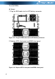
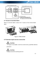
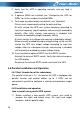
Figure 3-17. Plug the EBM cable into the UPS battery connector
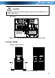
3.6 Tower Setup
Tower setup as be
low:
Figure 3-18. Tower setup
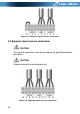
CA
UTION:
Please connect the EB
M to
protective ground with
8 AWG
wire for
EBM mode
l firstly.
1
...
...
20
21
22
23
24
...
...
64