Line Interactive UPS PowerWalker VI 1000RT LCD PowerWalker VI 1000E/RT LCD PowerWalker VI 1500RT LCD PowerWalker VI 2000RT LCD PowerWalker VI 3000RT LCD Manual EN, DE, FR, PL EN
IMPORTANT SAFETY INSTRUCTIONS SAVE THESE INSTRUCTIONS – This manual contains important instructions for models PowerWalker VI 1000/1000E/1500/2000/3000 RT LCD that should be followed during installation and maintenance of the UPS and batteries. • EN This product is specially designed for PCs and it is not recommended for use in any life-supporting system and other specific important equipment. • This equipment can be operated by any individual with no previous training.
• Remove watches, rings, or other metal objects from the hand. • Use tools with insulated handles. • Servicing of batteries should be performed or supervised by personnel knowledgeable of batteries and the required precautions. Keep unauthorized EN personnel away from batteries. • When replacing batteries, replace with the same type and number of the sealed • The maximum ambient temperature rating is 40°C.
CONTENTS 1. Introduction ······························································································· 5 2. Safety Warning ··························································································· 2 EN 2.1 Description of Commonly Used Symbols ····················································· 2 3. Installation ································································································· 3 3.
1. Introduction This line-interactive series is compact and pure sine wave UPS and it is designed for essential applications and environment, such as desktops, servers, workstations, and other networking equipments. These models are available in the output ratings of 1000VA/1500VA/2000VA/3000VA. The series protects your sensitive electronic equipments against power problems including power sags, spike, brownouts, line noise, undervoltage, overvoltage and blackouts.
2. Circuit Symbols Configuration and Commonly used EN Following figure shows the basic internal circuit configuration of the UPS 2.1 Description of Commonly Used Symbols Some or all of the following Notations may be used in this manual and may appear in your application process. Therefore, all users should be familiar with them and understand their explanations. Table1.
3. Installation 3.1 Inspection of Unit Inspect the UPS upon receiving. If the UPS is apparently damaged during the shipment, please keep the box and packing material in original form for the carrier and notify the carrier and dealer immediately. 3.2 Unpacking the Cabinet To unpack the system: 1. Open the outer carton and remove the accessories packaged with the cabinet. 2. Carefully lift the cabinet out of the outer carton and set it on a flat, stable surface. 3.
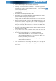
Use the following procedure to install UPS in UPS stands. 1. Slide down the UPS vertically and put two UPS stands at the end of the tower. 2. Place down the UPS into two stands carefully.
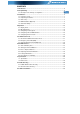
3. Pull out the LCD box and rotate it in a clockwise direction to 90 degree and then push it back in the front panel.
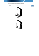
Rack-mount setup The series can be installed in 19 inches racks. Both the UPS and external battery enclosure need 2U of valuable rack space. Use the following procedure to install UPS in a rack. 1. Align the mounting ears with screw holes on the side of the UPS, and tighten the screw. 2. Assemble the rack rails with the rack-mounting.
3. Slide in the UPS into the rack rail and lock it in the rack enclosure. EN 4. Tighten the screw, and the load can then be connected.
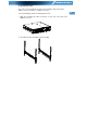
3.4 EBM Installation (Optional) Connecting the EBM in Tower form: 1. Slide down the UPS and EBM vertically and place two UPS stands with the extend part at the end of the tower. 2. Tighten the screw on the metal sheet for stabilization 3.
4. Take off the front panel, and connect the battery terminal (A) from UPS to EBM terminal (B) shown as below. Users need to remove the small gate(C) on side of the front panel to allow the outlet wire of the EBM to pass through the gate and then reassemble front panel. EN A C B Connecting the EBM in a rack form 1. Using the same method as assembling UPS in a rack form, assemble EBM into the rack-mounting on the top or bottom of the UPS.
2. Connect the earth line from UPS (port A ) to EBM (port B ) EN B A 3. Take off the LCD box, and unscrew the internal screws.
4. Take off the front panel, and connect the battery terminal (A) from UPS to EBM terminal (B) shown as below. Users need to remove the small gate(C) on side of the front panel to allow the outlet wire of the EBM to pass through the gate and then reassemble front panel. EN B A C 5. After installing the UPS into rack, the load can then be connected to UPS. Please make sure the load equipment is turned off before plugging all loads into the output receptacle.
Connecting multiple EBMs in Tower form 1. Connect Earth line between UPS and the first EBM, and then connect Earth Line between the first EBM and the second EBM. EN 2. Take off the front panel, and connect the battery terminal (A) from UPS to EBM terminal (B) shown as below. And then connect the battery terminal (D) from the first EBM to the battery terminal (E) from the second EBM.
Connecting the Multiple EBMs in rack form 1. Connect Earth line between UPS and the first EBM, and then connect Earth Line between the first EBM and the second EBM. EN 2. Take off the front panel, and connect the battery terminal (A) from UPS to EBM terminal (B) shown as below. And then connect the battery terminal (D) from the first EBM to the battery terminal (E) from the second EBM.
3.5 UPS Initial Startup To start up the UPS: 1. Verify that the internal batteries are connected. If optional EBMs are installed, verify that the EBMs are connected to the UPS. 2. Plug the equipment to be protected onto the UPS, but do not turn on the protected equipment. 3. Plug in the UPS input power cord. The UPS front panel display illuminates and UPS status display shows “STbY” 4. Press and hold the button display changes to “NORM” more than 3 seconds. The UPS status 6.
4. Operation 4.1 Display Panel The UPS has a four-button graphical LCD with dual color backlight. Standard back-light is used to light up the display with black text and a blue background. When the UPS has a critical alarm, the backlight changes the background to red. See Figure below: Control Buttons functions: There are four buttons on the control panel.
The following table describes the functions of the LCD control buttons. Table2. Description of control button Control Button Switch Function EN --To turn on/off the UPS Press and hold the button ON/OFF more than 3 seconds. --To release the UPS from faulty mode Cut off input power and then press and hold the button more than 2 seconds to shut down the UPS. --To perform basic function test Press and hold the button UPS Test Alarm Silence for 3 seconds.
LCD display functions: The following table describes the functions of the LCD display. Table3. Description of LCD display function No. Description EN Function Input frequency and voltage Indicate the value of input frequency and voltage Input plug indicator Light on when the input power is at no loss. Output frequency and voltage Indicate the value of output frequency and voltage Output plug indicator The UPS has two groups of outlets.
UPS Status Display String Description: The following table shows the description of the LCD display string: Table4.
4.2 Operating Mode Normal range mode: Under Input mode the UPS accepts AC input voltage range for +/-20%. Generator mode: Under generator mode, the low frequency transfer point can go as low as 40Hz and as high as 70Hz before being transferred to battery mode. Wide range mode: Under Input settings mode, the UPS accepts AC input voltage range for -30% ~ +20%.
will return to current setting item. 6. Exit Settings mode: Press and hold the Enter button button for 0.5 second to exit setting mode. for 3 seconds or 4.4 Configuring UPS for EBM Numbers To ensure the LCD displays the correct battery volume, configure the UPS for the correct number of EBMs: Note: 1 KVA E-model has no EBM,can not configure. 1. Enter settings mode: Press more than 3 seconds to enter setting mode. 2. Select settings items: Press to select setting items as “EbM”. 3.
5. Communication Port 5.1 RS-232 and USB Communication Ports To establish communication between the UPS and a computer, connect your computer to one of the UPS communication ports using an appropriate communication cable. When the communication cable is installed, power management software can exchange data with the UPS. The software polls the UPS for detailed information on the status of the power environment.
Caution: EN The EPO must not be connected to any utility connected circuits. Reinforced insulation to the utility is required. The EPO Switch must have a minimum rating of 24Vdc and 20mA and be a dedicated latching-type switch not tied into any other circuit. The EPO signal must remain active for at least 20ms for proper operation Wire Function EPO EPO Connections Terminal Wire Size Rating 4-0.32mm2(12-22AWG) Suggested Wire Size 0.
6. UPS Maintenance EN 6.1 UPS and Battery Care For the best preventive maintenance, keep the area around the UPS clean and dust-free. If the atmosphere is very dusty, clean the outside of the system with a vacuum cleaner. For long battery life, keep the UPS at an ambient temperature of 25°C (77°F) 6.2 Storing the UPS and Batteries When the UPS is intended to store for a long period, recharge the battery every 6 months by connecting the UPS to utility power.
batteries. Do not dispose of battery in a fire. Batteries may explode when exposed to flame. Proper disposal of batteries is required. Refer to your local codes for disposal requirements. Do not open or mutilate the battery. Released toxic electrolyte is harmful to skin and eyes. Note: If you are not qualified service personnel to replace the battery, do not attempt to open the battery cabin. Please call local dealer or distributor immediately. 6.
4. Remove the right inner battery bracket. EN 5. Pull the battery pack out onto flat area. 6. Install new battery pack into UPS. 7. Screw up the battery bracket and reconnect the battery cable A and B 8. Re-install the front panel back to UPS.
6.5 Testing New Batteries For a battery test, please check: The batteries must be fully charged. The UPS must be in Normal mode with no active alarms. Don’t take on/off the load. To test batteries: 1. Connect the UPS to utility power for at least 48 hours to charge the batteries. 2. Press and hold the button 10 seconds to start the battery test. The status display string shows “TEST” 6.6 Recycling the Used Battery: Warning: Never dispose the batteries in a fire. It may explode.
7. Specification 7.1 Specification EN Table7. Electrical Specification Model Capacity Watt 1000 1000S 1000E 1500 1500S 2000 2000S 3000 3000S 900W 900W 1350W 1800W 2700W Input voltage range 161-276VAC Input 50/60Hz ±5Hz for Normal Mode 40-70Hz for Generator Mode Frequency range Voltage Output 220/230/240VAC Voltage Regulation (Batt. Mode) ±5% Frequency 50Hz or 60Hz Waveform Pure sinewave 110% -0%, +8%: shutdown after 3 minutes.
Table8. Indicators and Audible alarm AC Mode NORM---normal mode Backup Mode EN Show “bATT” and sounding every 4 seconds Load/Battery Level LCD showing Indicator UPS Fault LCD show red screen and “ **** ” Overload LCD show red screen and “ OVLD ” Low Battery LCD show red screen and “ bTLW ” Backup Mode Audible alarm Sounding every 4seconds Low Battery Sounding every second UPS Fault Continuously Sounding Overload Sounding every second Battery Replacement Sounding every second Table9.
7.2 Rear Panels The UPS rear panel description table and pictures are shown as below: EN Function(1000VA &1000EVA & 1500VA) AC Output Modem/Network Surge Protection Intelligent Slot for SNMP or AS/400 card AC Input RS232 / Dry-Contact Communication Port USB Port EPO Earth Line Port 3 4 OUT INTERFACE OPTION IN LS2 OUT PUT 25KV~ 10A NETWORK/TELEPHONE PROTECTION 2 LS1 OUT PUT 25KV~ 10A 1 INPUT 220-240V~ No.
Function(2K/3KVA Standard & Supper charger model) AC Output Modem/Network Surge Protection Intelligent Slot for SNMP or AS/400 card Fan AC Input RS232 / Dry-Contact Communication Port USB Port EPO Earth Line Port 1 3 2 5 4 I NPUT 220-240V~ OUT IN LS2 OUT PUT 25KV~ 10A NETWORK/ TELEPHONE PROTECTI ON LS1 OUT PUT 25KV~ 10A I NTERFACE OPTI ON RS232 1 USB 6 EPO 8 7 9 2000VA Standard model rear panel 1 3 2 5 4 1 RS232 6 USB 7 EPO 8 2000VA Super charger model rear panel I NPUT 220-
1 1 2 3 4 5 1 OUT IN NETWORK/ TELEPHONE PROTECTI ON EN RS232 6 USB 7 EPO 8 I NPUT 220-240V~ LS2 OUT PUT 25KV~ 10A 25KV 16A ~ LS1 OUT PUT 25KV~ 10A I NTERFACE OPTI ON 9 3000VA Standard & Supper charger model rear panel The EBM rear panel description table and picture are shown as below: No.
8. Trouble Shooting 8.1 Audible Alarm Trouble Shooting Indication Sounding every 4 seconds Sounding every Second and “bATL” on screen Sounding every second and “OVLD” on screen Continuously sounding and red display Cause The UPS is on battery mode Solution Check the input voltage The battery voltage is low Save your work and turn off your equipment Output overload Check load level indicator and remove some load The UPS fails Please contact your local dealer 8.
9. Software Installation WinPower is UPS monitoring software, featuring user-friendly interface to monitor and control your UPS. This unique software provides complete power EN protection for computer system while power failure. With the software users can monitor any UPS status on the same LAN.
Line Interactive USV PowerWalker VI 1000RT LCD PowerWalker VI 1000E/RT LCD PowerWalker VI 1500RT LCD PowerWalker VI 2000RT LCD PowerWalker VI 3000RT LCD Bedienungsanleitung DE, EN, FR, PL DE
WICHTIGE SICHERHEITSHINWEISE DE BEWAHREN SIE DIESE ANLEITUNG GUT AUF – Dieses Handbuch enthält wichtige Anweisungen für die Modelle PowerWalker VI 1000/1000E/1500/ 2000/3000 RT LCD, die während Installation und Wartung der USV-Geräte und Akkus eingehalten werden müssen. • Dieses Produkt wurde speziell für PC’s entwickelt und wird nicht für den Einsatz wie etwa für Lebenserhaltungssysteme und andere wichtige Geräte empfohlen. • Dieses Gerät kann von Jedermann ohne vorherige Ausbildung betrieben werden.
kontaktieren Sie bitte den Händler. • Ein interner Kurzschluss in dem USV-Gerät führt zu Gefahren wie z.B. Stromschlag oder Feuer. Um die Gefahr eines Stromschlages zu vermeiden, bitte niemals Flüssigkeitsbehälter (z.B. ein Wasserglas) auf dem USV-GerätDE abstellen. • Werfen Sie die Batterie(n) nicht in offenes Feuer. Der Akku könnte explodieren. • Öffnen oder zerstören Sie die Batterie(n) nicht. Freigesetzter Elektrolyt kann Haut und Augen schädigen. Es kann giftig sein.
kontaktieren Sie Ihren Händler. • Verwenden Sie das Gerät nicht in einer der folgenden Umgebungen: o Jegliche Bereiche mit brennbaren Gasen, ätzenden Substanzen oder DE hoher Staubbelastung. o Jegliche Bereiche, in denen ungewöhnlich hohe oder niedrige Temperaturen vorherrschen (über 40 °C oder unter 0 °C) und mit einer Feuchtigkeit von mehr als 90%. o Jegliche Bereiche mit direkter Sonneneinstrahlung oder in der Nähe von Heizgeräten/Heizungen. o o • Falls Jegliche Bereiche mit starken Vibrationen.
INHALT 1. EINFÜHRUNG ····························································································· 5 2. SCHALTUNGSKONFIGURATION UND HÄUFIG VERWENDETE SYMBOLE ········· 7 DE 2.1 Description of Commonly Used Symbols ····················································· 7 3. INSTALLATION ··························································································· 8 3.1 ÜBERPRÜFUNG DES GERÄTS ································································ 8 3.
1. Einführung Diese Line-Interactive-Serie ist eine kompakte USV mit reiner Sinuswelle und ist für wichtige Anwendungen und Umgebungen wie Desktops, Server, Workstations und andere Netzwerk-Geräte konzipiert. Diese Modelle sind mit den Leistungsstufen 1000VA, 1500VA, 2000VA und 3000VA erhältlich.
2. Schaltungskonfiguration und häufig verwendete Symbole DE Folgende Abbildung zeigt die grundlegenden interne Schaltungskonfiguration der USV 2.1 Beschreibung der häufig verwendeten Symbole In diesem Handbuch können einige oder alle der folgenden Notationen verwendet werden und in Ihrem Anwendungsprozess vorkommen. Deshalb sollten alle Anwender mit ihnen vertraut sein und ihre Erklärungen verstehen. Tabelle 1.
3. Installation 3.1 Überprüfung des Geräts Überprüfen Sie die USV bei Empfang. Wenn die USV während des Transport offensichtlich beschädigt wurde, bewahren Sie den Karton und das Verpackungsmaterial in der ursprünglichen Form für den Spediteur auf und benachrichtigen Sie sofort den Spediteur und den Händler. 3.2 Auspacken des Schranks Auspacken des Systems: 1. Öffnen Sie den äußeren Karton und entfernen Sie das Zubehör, das zusammen mit dem Schrank eingepackt ist. 2.
Gehen Sie folgendermaßen vor, um die USV in den USV-Ständern zu installieren. 1. Schieben Sie die USV senkrecht nach unten und stellen Sie zwei USV-Ständer am Ende des Towers auf. 2. Setzen Sie die USV vorsichtig in die zwei Ständer.
3. Ziehen Sie das LCD-Feld heraus, drehen Sie es im Uhrzeigersinn um 90 Grad und schieben Sie es in die Frontplatte zurück.
Rack-Montage Die Serie kann in 19-Zoll-Racks eingebaut werden. Sowohl die USV als auch externe Batteriegehäuse benötigen 2U wertvollen Platz im Rack. Gehen Sie folgendermaßen vor, um USV in einem Rack zu installieren. 1. Richten Sie die Montageösen an den Bohrungen an der Seite der USV aus und ziehen Sie die Schraube an. 2. Bauen Sie die Rack-Schienen mit der Rack-Halterung zusammen.
3. Schieben Sie die USV in die Rack-Schienen und lassen Sie sie im Rack-Gehäuse einrasten. 4. Ziehen Sie die Schraube an, dann kann die Last angeschlossen werden.
3.4 EBM-Installation (Optional) Anschließen des EBM bei Tower-Montage: 1. Schieben Sie USV und EBM senkrecht nach unten und setzen Sie zwei USV-Ständer mit dem verlängerten Teil auf das Ende des Towers. 2. Ziehen Sie zur Stabilisierung die Schraube auf dem Blech an 3.
4. Nehmen Sie die Frontplatte ab und schließen Sie die Batterieklemme (A) von der USV wie unten dargestellt am EBM-Terminal (B) an. Benutzer müssen die kleine Tür (C) an der Seite der Frontplatte entfernen, damit der Ausgangsdraht des EBM durch die Tür verlegt werden kann, dann muss die Frontplatte wieder angebracht werden. A C B Anschließen des EBM bei Rack-Montage 1.
2. Verbinden Sie die Erdungsleitung von der USV (Anschluss A) mit dem EBM (Anschluss B) B A 3. Nehmen Sie das LCD-Feld und lösen Sie die inneren Schrauben.
DE 4. Nehmen Sie die Frontplatte ab und schließen Sie die Batterieklemme (A) von der USV wie unten dargestellt am EBM-Terminal (B) an. Benutzer müssen die kleine Tür (C) an der Seite der Frontplatte entfernen, damit der Ausgangsdraht des EBM durch die Tür verlegt werden kann, dann muss die Frontplatte wieder angebracht werden. B A C 5. Nach der Installation der USV im Rack kann die Last der USV angeschlossen werden.
Anschließen mehrerer EBM bei Tower-Montage 1. Verbinden Sie die Erdungsleitung zwischen USV und dem ersten EBM, und dann die Erdungsleitung zwischen dem ersten und dem zweiten EBM. 2. Nehmen Sie die Frontplatte ab und schließen Sie die Batterieklemme (A) von der USV wie unten dargestellt am EBM-Terminal (B) an. Und verbinden Sie dann die Batterieklemme (D) vom ersten EBM mit der Batterieklemme (E) vom zweiten EBM.
Anschließen mehrerer EBM bei Rack-Montage 1. Verbinden Sie die Erdungsleitung zwischen USV und dem ersten EBM, und dann die Erdungsleitung zwischen dem ersten und dem zweiten EBM. 2. Nehmen Sie die Frontplatte ab und schließen Sie die Batterieklemme (A) von der USV wie unten dargestellt am EBM-Terminal (B) an. Und verbinden Sie dann die Batterieklemme (D) vom ersten EBM mit der Batterieklemme (E) vom zweiten EBM.
3.5 Erstmalige Inbetriebnahme der USV So wird die USV gestartet: 1. Stellen Sie sicher, dass die internen Batterien angeschlossen sind. Wenn optionale EBMs installiert werden, überprüfen Sie, ob die EBMs an die USV angeschlossen sind. 2. Stecken Sie die zu schützenden Geräte an der USV ein, aber schalten Sie diese Geräte nicht ein. 3. Stecken Sie das Eingangsnetzkabel der USV ein. Das USV-Frontdisplay leuchtet und die USV-Status-Anzeige zeigt "STbY" mindestens 3 Sekunden gedrückt. Die 4.
4. Betrieb 4.1 Anzeigefeld Die USV verfügt über eine Grafik-LCD mit vier Tasten und zweifarbiger Hintergrundbeleuchtung. Bei der Standard-Hintergrundbeleuchtung zeigt die Anzeige schwarzen Text und einen blauen Hintergrund. Wenn an der USV ein kritischer Alarm auftritt, wird der Hintergrund der Beleuchtung rot. Siehe Abbildung unten: Funktionen der Bedientasten: Es gibt auf dem Bedienfeld vier Tasten.
Die folgende Tabelle beschreibt die Funktionen der LCD-Bedientasten. Tabelle 2. Beschreibung der Bedientaste Bedienta ste Schalter Funktion DE --Ein-/Ausschalten der USV Halten Sie die Taste gedrückt. ein/aus mindestens 3 Sekunden --Freigabe des Fehlerzustands der USV Stromzufuhr trennen und dann die Taste mehr als 2 Sekunden gedrückt halten, um die USV abzuschalten.
Funktionen der LCD-Anzeige: Die folgende Tabelle beschreibt die Funktionen der LCD-Anzeige. Tabelle 3. Beschreibung der Funktionen der LCD-Anzeige Nr. Beschreibung Eingangs-frequenz und spannung Eingangssteckeranzei ge Ausgangs-frequenz und spannung Funktion Geben Sie den Wert für Eingangs-frequenz und spannung an Leuchtet, wenn die Eingangsleistung keinen Verlust aufweist.
Text zur Beschreibung des USV-Status:Die folgende Tabelle enthält die Beschreibung des Texts der LCD-Anzeige: Tabelle 4.
4.2 Betriebsmodus Modus Normaler Bereich: Im Eingangsmodus akzeptiert die USV einen AC-Eingangsspannungsbereich von +/-20%. Generatormodus: Im Generator-Modus kann der Niedrigfrequenzgang bis auf 40Hz heruntergehen und bis auf 70Hz herauf, bevor der Übergang zum Batterie-Modus erfolgt. Modus Großer Bereich: In den Eingangseinstellungen akzeptiert die USV einen AC-Eingangsspannungsbereich für -30% ~ +20%.
4. Einstellungswert wählen: Drücken Sie die Taste Select , um den Einstellungswert auszuwählen. Wählen Sie den Wert [001] oder [000], um das gewünschte Lastsegment auf ON oder OFF zu setzen. 5. Einstellungen bestätigen: Halten Sie die Taste Enter eine Sekunde gedrückt, dann kehrt die USV zum aktuellen Einstellungsobjekt zurück. 3 Sekunden 6. Einstellungsmodus beenden: Halten Sie die Taste Enter oder die Taste 0,5 Sekunden gedrückt, um den Einstellungsmodus zu verlassen. 4.
3. Einstellungsobjekt öffnen: Drücken Sie mindestens eine Sekunde, um das Einstellungsobjekt zu öffnen. , um "001" 4. Einstellungswert wählen: Drücken Sie die Taste Select auszuwählen. 5. Einstellungen bestätigen: Halten Sie die Taste Enter eine Sekunde lang gedrückt, daraufhin kehrt die USV zum aktuellen Einstellungsobjekt zurück. 3 Sekunden 6. Einstellungsmodus beenden: Halten Sie die Taste Enter oder die Taste 0,5 Sekunden gedrückt, um den Einstellungsmodus zu verlassen. DE 5.
5.2 Notabschaltung (Emergency Power Off, EPO) Die Notabschaltung (EPO) wird zum Abschalten der Last aus der Ferne verwendet. Diese Funktion kann zum Herunterfahren der Last im Notfall verwendet werden. DE Das 1 KVA E-Modell besitzt keine EPO-Funktion Warnung: Diese Schaltung muss durch verstärkte Isolierung von gefährlichen Stromkreisen getrennt werden. Vorsicht: Die EPO darf nicht an Netzstromkreise angeschlossen werden. Es ist eine verstärkte Isolierung zum Netz erforderlich.
6. Wartung der USV DE 6.1 Pflege von USV und Batterie Die beste vorbeugende Wartung ist, den Bereich um die USV sauber und staubfrei zu halten. Wenn die Atmosphäre sehr staubig ist, reinigen Sie die Außenseite der Anlage mit einem Staubsauger. Für eine lange Lebensdauer der Batterie stellen Sie die USV bei einer Umgebungstemperatur von 25°C auf. 6.
Wenn die Akkus ersetzt werden, ersetzen Sie diese mit dem gleichen Typ und der gleichen Anzahl Batterien oder Akkumulatoren. Wenden Sie sich an den Kundendienst, um neue Batterien zu bestellen. Werfen Sie die Batterien nicht ins Feuer. Batterien können explodieren, wenn sie Flammen ausgesetzt werden. Batterien müssen fachgerecht entsorgt werden. Folgen Sie Ihren örtlichen Entsorgungsvorschriften. Öffnen oder zerstören Sie die Batterie nicht. Freigesetzter toxischer Elektrolyt kann Haut und Augen schädigen.
4. Entfernen Sie die Halterung der rechten inneren Batterie. DE 5. Ziehen Sie die Batterie auf eine ebene Fläche heraus. 6. Setzen Sie die neue Batterie in die USV ein. 7. Schrauben Sie die Batteriehalterung an und schließen Sie die Batteriekabel A und B wieder an. 8. Setzen Sie die Frontplatte wieder auf die USV.
6.5 Testen neuer Batterien Für einen Batterietest überprüfen Sie bitte Folgendes: DE Die Batterien müssen vollständig aufgeladen sein. Die USV muss sich im Normal-Modus ohne aktive Alarme befinden. Schalten Sie keine Last zu/ab. Testen der Batterien: 1. Schließen Sie die USV für mindestens 48 Stunden an das Stromnetz an, um die Batterien aufzuladen. 2. Halten Sie die Taste 10 Sekunden gedrückt, um den Batterietest zu starten. Die Statusanzeige zeigt die Zeichenfolge “TEST” 6.
7. Spezifikation 7.1. Spezifikation DE Tabelle 7. Elektrische Spezifikation Modell Leistung Watt Eingang Eingangsspannungsbereich Frequenzbereich 1000VA 1000VA E 1500VA 2000VA 3000VA 900W 900W 1350W 1800W 2700W 161-276 V AC 50/60Hz ±5Hz für Normal-Modus 40-70Hz für Generator-Modus Spannung Ausgang 220/230/240VAC Spannungsregulierung (Batt. -Modus) ±5% Frequenz 50 Hz oder 60 Hz Wellenform Reine Sinuswelle Netzbetrieb 110% -0%, +8%: Abschalten nach 3 Minuten.
Tabelle 8.
7.2 Rückseiten DE Der Tabelle mit der Beschreibung der Rückseite der USV und Abbildungen werden wie unten dargestellt: Funktion(1000VA &1500VA) AC-Ausgang Überspannungsschutz Modem/Network Intelligenter Einschub für SNMP- oder AS/400-Karte AC-Eingang RS232 / Kommunikationsanschluss mit potentialfreien Kontakten USB Schnittstelle EPO Schutzleiteranschluss LS2 OUT PUT 25KV~ 10 A 1 3 4 OUT INTERFACE OPTION IN NETWORK/TELEPHONE PROTECTION 2 LS1 OUT PUT 25KV~ 10A 1 INPUT 220-240V~ Nr.
25KV 16A ~ 1 IN OUT LS2 OUT PUT 25KV~ 10A LS1 OUT PUT 25KV~ 10A NETWORK/ TELEPHONE PROTECTI ON LS2 OUT PUT 25KV~ 10A LS1 OUT PUT 25KV~ 10A NETWORK/ TELEPHONE PROTECTI ON IN RS232 6 6 RS232 RS232 6 3 I NTERFACE OPTI ON USB 7 USB 7 EPO 8 EPO 8 I NTERFACE OPTI ON 3 3 I NTERFACE OPTI ON USB 7 EPO 8 4 4 4 I NPUT 220-240V~ 9 9 I NPUT 220-240V~ OUT 2 OUT 2 2 IN 2000VA Standard-Modell, Rückseite NETWORK/ TELEPHONE PROTECTI ON 2000VA Supercharger-Modell, Rückseite L
Die Tabelle mit der Beschreibung der EBM-Rückseite und Abbildungen werden wie unten dargestellt: Nr.
8. Fehlerbehebung 8.1 Fehlerbehebung bei akustischem Alarm Anzeige Ertönt alle 4 Sekunden Ertönt jede Sekunde und "bATL" wird angezeigt Ertönt jede Sekunde und "OVLD" wird angezeigt Ertönt kontinuierlich und rote Anzeige Ursache Die USV ist im Batteriemodus Lösung DE Eingangsspannung prüfen Batteriespannung niedrig Arbeit speichern und Geräte ausschalten Ausgangsüberlastung Lastniveauanzeige prüfen und etwas Last entfernen USV-Fehler Bitte wenden Sie sich an Ihren Händler vor Ort 8.
9. Softwareinstallation WinPower ist die Überwachungssoftware der USV, mit benutzerfreundlicher Schnittstelle zur Überwachung und Steuerung Ihrer USV. Diese einzigartige Software bietet kompletten DE Leistungsschutz für Ihr Computer-System bei Stromausfall. Mit der Software können Benutzer jeden USV-Status auf dem gleichen LAN überwachen. Darüber hinaus kann eine USV Sicherheits für mehr als einen Computer auf dem gleichen LAN gleichzeitig liefern, z.B.
Onduleur en ligne interactif PowerWalker VI 1000RT LCD PowerWalker VI 1000E/RT LCD PowerWalker VI 1500RT LCD PowerWalker VI 2000RT LCD PowerWalker VI 3000RT LCD Manuel FR, EN, PL, DE FR
INSTRUCTIONS DE SÉCURITÉ IMPORTANTES CONSERVEZ CES INSTRUCTIONS – Ce manuel contient des instructions importantes pour les modèles PowerWalker VI 1000/1000E/1500/2000/3000 RT LCD qui doivent être respectée durant l'installation et l'entretien de l'onduleur et des batteries. • Ce produit a été conçu spécialement pour être utilisé avec des ordinateurs et, par conséquent, n'est pas recommandé pour une utilisation avec un équipement de survie quel qu'il soit ni avec tout autre équipement spécifique important.
dangers tels qu'une électrocution. Si une révision ou un remplacement de la batterie sont nécessaires, veuillez contacter le distributeur • Un court-circuit interne de l'onduleur entraîne des dangers comme une électrocution ou un incendie ; par conséquent, aucun récipient d'eau (verre d'eau, par exemple) ne doit être placé au-dessus de l'onduleur afin d'éviter ces dangers. • Ne jetez pas les batteries au feu. Elles pourraient exploser. • Ne pas ouvrir ni démanteler les batteries.
• En cas de fumée sortant de l'appareil, coupez rapidement l'alimentation secteur et prenez contact avec le distributeur. • Ne pas conserver ni n'utiliser ce produit dans l'un des environnements suivants : o Toute zone où se trouve du gaz combustible, des substances corrosives ou une densité de poussière élevée. o Toute zone se trouvant à une température extrêmement élevée ou basse (supérieure à 40 °C ou inférieure à 0 °C) et où le degré d'humidité dépasse 90 %.
TABLE DES MATIÈRES 1. INTRODUCTION ····················································································· 6 2. CONFIGURATION DU CIRCUIT ET SYMBOLES D'USAGE COURANT ············ 7 2.1 DESCRIPTION DES SYMBOLES D'USAGE COURANT ······························· 7 3. INSTALLATION ······················································································ 8 3.1 INSPECTION DE L'APPAREIL ·························································· 8 3.
1. Introduction Cette série d'onduleurs en ligne interactifs possède une forme compacte et fonctionne en onde sinusoïdale pure. Elle est conçu pour les applications et environnements essentiels, comme les postes de travail, les serveurs, les stations de travail et les autres équipements réseau. Ces modèles sont disponibles avec une puissance nominale de sortie de 1000 VA/1500VA/2000VA/3000VA.
2. Configuration du circuit et symboles d'usage courant FR La figure suivante illustre la configuration de circuit interne de base de l'onduleur 2.1 Description des symboles d'usage courant Les notations suivantes peuvent être utilisées en partie ou dans leur intégralité et peuvent apparaître dans votre processus d'application. Par conséquent, tous les utilisateurs doivent se familiariser avec elles et comprendre leurs descriptions. Tableau 1.
3. Installation 3.1 Inspection de l'appareil Inspectez l'onduleur dès sa réception. Si l'onduleur est visiblement endommagé durant l'expédition, veuillez conserver la boîte et le matériau d'emballage original pour le transporteur et avertir immédiatement le transporteur et le vendeur. 3.2 Déballage du module Pour déballer le système : 1. Ouvrez le carton extérieur et retirez les accessoires emballés avec le module. 2.
Utilisez la procédure suivante pour installer l'onduleur dans les supports. 1. Faites glisser l'onduleur vers le bas à la verticale et placez deux supports au bas de la tour. 2. Enfoncez l'onduleur soigneusement dans les deux supports.
3. Sortez le boîtier LCD et faites-le tourner de 90 degrés vers la droite puis remettez-le dans la façade.
Installation dans une baie La série peut être installée dans une baie de 19 pouces. L'onduleur et le boîtier de la batterie externe ont besoin de 2U d'espace libre. Utilisez la procédure suivante pour installer l'onduleur dans une baie. 1. Alignez les oreilles de montage avec les trous de vis sur le côté de l'onduleur et serrez les vis. 2. Assemblez les rails pour baie avec le support de la baie.
3. Enfoncez l'onduleur dans le rail pour baie et verrouillez-le dans le boîtier de la baie. FR 4. Serrez la vis et raccordez la charge.
3.4 Installation de l'EBM (en option) Raccordement de l'EBM en mode tour : 1. Faites glisser l'onduleur et l'EBM vers le bas à la verticale et placez deux supports sur la partie allongée au bas de la tour. 2. Serrez la vis sur la tôle métallique pour la stabilisation 3.
4. Retirez la façade et raccordez la borne de batterie (A) de l'onduleur à la borne de l'EBM (B) illustrée ci-dessous. Vous devez retirer la petite trappe (C) sur le côté de la façade pour permettre au fil de sortie de l'EBM de passer à travers la trappe et de rejoindre la façade. FR A C B Raccordement de l'EBM en mode baie 1. Utilisez la même méthode que pour le montage de l'onduleur dans une baie, puis assemblez l'EBM dans le support de la baie au-dessus ou au-dessous de l'onduleur.
2. Raccordez la ligne de terre provenant de l'onduleur (port A ) à l'EBM (port B) FR B A 3. Retirez le boîtier LCD et dévissez les vis internes.
4. Retirez la façade et raccordez la borne de batterie (A) de l'onduleur à la borne de l'EBM (B) illustrée ci-dessous. Vous devez retirer la petite trappe (C) sur le côté de la façade pour permettre au fil de sortie de l'EBM de passer à travers la trappe et de rejoindre la façade. FR B A C 5. Après l'installation de l'onduleur dans la baie, la charge peut être raccordée à l'onduleur.
Raccordement de plusieurs EBM en mode tour 1. Raccordez la ligne de terre entre l'onduleur et le premier EBM, puis raccordez la ligne de terre entre le premier EBM et le deuxième EBM. FR 2. Retirez la façade et raccordez la borne de batterie (A) de l'onduleur à la borne de l'EBM (B) illustrée ci-dessous. Connectez ensuite la borne de batterie (D) du premier EBM à la borne de batterie (E) du deuxième EBM.
Raccordement de plusieurs EBM en mode baie 1. Raccordez la ligne de terre entre l'onduleur et le premier EBM, puis raccordez la ligne de terre entre le premier EBM et le deuxième EBM. FR 2. Retirez la façade et raccordez la borne de batterie (A) de l'onduleur à la borne de l'EBM (B) illustrée ci-dessous. Connectez ensuite la borne de batterie (D) du premier EBM à la borne de batterie (E) du deuxième EBM.
3.5 Mise en marche initiale de l'onduleur Pour mettre en marche l'onduleur : 1. Vérifiez que les batteries internes sont connectées. Si des EBM en option sont installés, vérifiez que les EBM sont connectés à l'onduleur. 2. Branchez l'équipement à protéger sur l'onduleur, mais ne mettez pas en marche l'équipement protégé. 3. Branchez le cordon d'alimentation d'entrée de l'onduleur. L'écran en façade de l'onduleur s'allume et l'écran d'état de l'onduleur affiche « STbY » 4.
4. Utilisation 4.1 Écran L'onduleur possède un écran LCD à quatre boutons avec un rétro-éclairage bicolore. Le rétro-éclairage standard est utilisé pour afficher un texte noir sur fond bleu à l'écran. Lorsque l'onduleur active une alarme critique, le rétro-éclairage devient rouge. Voir la figure ci-dessous : Fonctions des boutons de contrôle : Le panneau de commande comprend quatre boutons.
Le tableau suivant décrit les fonctions des boutons de contrôle de l'écran LCD. Tableau 2. Description des boutons de contrôle Bouton de contrôle FR Interrupteur Fonction --Pour mettre en marche/arrêter l'onduleur MARCHE/ ARRÊT Maintenez le bouton 3 secondes. enfoncé pendant plus de -- Pour faire sortir l'onduleur du mode erreur Coupez l'alimentation d'entrée, puis maintenez enfoncé le bouton pendant plus de 2 secondes pour arrêter l'onduleur.
Remarque : Les évènements de la liste indiquée ci-dessous ne permettent pas de désactiver la sonnerie d'alarme : batterie faible, panne du ventilateur, dépassement de délai de défaut du ventilateur et surchauffe. FR Remarque : L'utilisateur peut désactiver la sonnerie d'alarme lorsqu'elle retentit, mais une sonnerie retentira toujours lorsqu'un nouvel évènement d'alarme se produira.
Fonctions de l'écran LCD : Le tableau suivant décrit les fonctions de l'écran LCD. Tableau 3. Description des fonctions de l'écran LCD Nº Description Fréquence et tension d'entrée Indicateur de prise d'entrée Fréquence et tension de sortie Indicateur de prise de sortie Inscription d'affichage de paramètre utilisateur/état de l'onduleur Indication d'avertissement Paramètres Fonction Indique la valeur de fréquence et tension d'entrée S'allume lorsque l'alimentation d'entrée est présente.
Description des inscriptions d'affichage d'état de l'onduleur : Le tableau suivant affiche la description des inscriptions de l'écran LCD : Tableau 4.
4.2 Mode de fonctionnement Mode plage normale : En mode d'entrée l'onduleur accepte une plage de tension d'entrée secteur de +/-20%. Mode générateur : En mode générateur, le point de transfert de fréquence basse peut aller jusqu'à 40 Hz et jusqu'à 70 Hz avant le passage en mode batterie. Mode plage étendue : En mode paramètres d'entrée l'onduleur accepte une plage de tension d'entrée secteur de -30% ~ +20%.
4. Sélectionner la valeur du paramètre : Appuyez sur le bouton sélection pour sélectionner la valeur des paramètres. Sélectionnez la valeur [001] ou [000] pour activer ou désactiver le segment de charge désiré. 5. Confirmer les paramètres : Maintenez enfoncé le bouton entrée pendant une seconde pour faire revenir l'onduleur à l'élément de paramètre actuel 6. Quitter le mode des paramètres : Maintenez enfoncé le bouton entrée pendant 0,5 seconde pour quitter le pendant 3 seconde ou le bouton mode paramètres.
2. Sélectionner les éléments des paramètres : Appuyez sur pour sélectionner les éléments de paramètre « GF ». pendant plus d'une 3. Entrer l'élément des paramètres : Appuyez sur seconde pour entrer l'élément du paramètre. 4. Sélectionner la valeur du paramètre : Appuyez sur le bouton sélection pour sélectionner « 001 ». 5. Confirmer les paramètres : Maintenez enfoncé le bouton entrée pendant une seconde pour faire revenir l'onduleur à l'élément de paramètre actuel. 6.
5. Port de communication 5.1 Ports de communication RS-232 et USB Pour établir la communication entre l'onduleur et un ordinateur, raccordez votre ordinateur à l'un des ports de communication de l'onduleur avec un câble de communication approprié. Lorsque le câble de communication est installé, le logiciel de gestion d'alimentation peut échanger des données avec l'onduleur. Le logiciel interroge l'onduleur pour obtenir les informations détaillées sur l'état de l'environnement d'alimentation.
Attention : L'EPO ne doit pas être raccordé à des circuits raccordés à l'alimentation. Une isolation renforcée pour le secteur est nécessaire. L'interrupteur EPO doit avoir une valeur nominale minimum de 24 Vcc et 20 mA et doit être un interrupteur dédié de type à verrouillage non raccordé à d'autres circuits.
6. Maintenance de l'onduleur 6.1 Entretien de l'onduleur et de la batterie Pour la meilleure maintenance préventive, maintenez la zone autour de l'onduleur propre et exempte de poussière. Si l'atmosphère est très poussiéreuse, nettoyez l'extérieur du système avec un aspirateur. Pour prolonger la durée de vie de la batterie, conservez l'onduleur à une température ambiante de 25 °C (77 °F) 6.
Lors du remplacement des batteries, les remplacer par le même type et nombre de batteries ou blocs batterie. Contactez votre représentant de service pour commander de nouvelles batteries. Ne jetez pas la batterie au feu. Les batteries peuvent exploser lorsqu'elles sont exposées à une flamme. Une mise au rebut appropriée des batteries est nécessaire. Consultez les normes locales pour connaître les exigences de mise au rebut. Ne pas ouvrir ni démanteler la batterie.
3. Débranchez le câble de l'onduleur et du bloc batterie. FR 4. Retirez le support de batterie interne droit. 5. Sortez le bloc batterie et placez-le sur une surface plane. 6. Installez un nouveau bloc batterie dans l'onduleur.
7. Vissez le support de batterie et rebranchez les câbles de batterie A et B. FR 8. Remontez la façade sur l'onduleur.
6.5 Test des nouvelles batteries Pour effectuer un test de batterie, veuillez contrôler les points suivants : Les batteries doivent être complètement chargées. L'onduleur doit être en mode normal, sans alarme active. Ne pas brancher/retirer la charge. Pour tester les batteries : 1. Branchez l'onduleur au secteur pendant au moins 48 heures afin de charger les batteries. 2. Maintenez enfoncé le bouton pendant 10 secondes pour lancer le test de la batterie. L'écran d'état affiche « TEST » 6.
7. Spécifications Techniques 7.1. Caractéristiques FR Tableau 7. Caractéristiques électriques Modèle Capacité Watt Entrée Plage de tensions d'entrée Plage de fréquences 1000 1000S 1000E 1500 1500S 2000 2000S 3000 3000S 900W 900W 1350W 1800W 2700W 161-276 VCA 50/60 Hz ± 5 Hz pour le mode normal 40-70Hz pour le mode générateur Tension Sortie 220/230/240 Vca Régulation de tension (Batt.
Tableau 8.
7.
Fonction (modèle 2000/3000 VA standard et à autonomie prolongée) 1 2 3 4 5 6 7 8 9 Sortie CA Protection de surtension pour modem/réseau Logement intelligent pour carte SNMP ou AS/400 Ventilateur Entrée secteur Port de communication RS-232/contact sec USB Port EPO Port de ligne de terre 1 3 2 FR 5 4 I NPUT 220-240V~ OUT IN LS2 OUT PUT 25KV~ 10A NETWORK/ TELEPHONE PROTECTI ON LS1 OUT PUT 25KV~ 10A I NTERFACE OPTI ON RS232 1 USB 6 EPO 8 7 9 Panneau arrière pour modèle 2000 VA standard 1
1 1 2 3 4 5 FR 1 OUT IN NETWORK/ TELEPHONE PROTECTI ON RS232 6 USB 7 EPO 8 I NPUT 220-240V~ LS2 OUT PUT 25KV~ 10A 25KV 16A ~ LS1 OUT PUT 25KV~ 10A I NTERFACE OPTI ON 9 Panneau arrière pour modèle 3000 VA standard et à autonomie prolongée Le tableau et l'illustration de description du panneau arrière de l'ECM sont fournis ci-dessous : Nº 1 Fonction (EBM 36 V et 72 V) Port de ligne de terre 1 1 Panneau arrière EBM 36 V et 72 V
8. Dépannage 8.
9. Installation du logiciel WinPower est une logiciel de monitorage d'onduleur qui inclut une interface intuitive pour surveiller et contrôler votre onduleur. Ce logiciel unique offre une protection électrique complète pour le système informatique durant une panne de courant. Avec le logiciel, vous pouvez surveiller l'état de n'importe quel onduleur sur le même réseau local.
Line Interactive UPS PowerWalker VI 1000RT LCD PowerWalker VI 1000E/RT LCD PowerWalker VI 1500RT LCD PowerWalker VI 2000RT LCD PowerWalker VI 3000RT LCD Instrukcja obsługi PL, EN, FR, DE PL
WAŻNE INSTRUKCJE DOTYCZĄCE BEZPIECZEŃSTWA ZACHOWAJ TĄ INSTRUKCJĘ – Niniejszy podręcznik zawiera ważne instrukcje dla modeli PowerWalker VI PL 1000/1500/2000/3000 RT LCD, które należy wykonywać podczas instalacji i konserwacji urządzenia i akumulatorów. • Ten produkt jest przeznaczony specjalnie do komputerów PC i nie zaleca się używania go w systemach podtrzymywania życia lub innych istotnych urządzeniach. • To urządzenie może być obsługiwane przez osobę bez specjalnego szkolenia.
• Wewnętrzne zwarcie systemu podtrzymywania napięcia prowadzi do zagrożeń, takich jak porażenie prądem lub pożar, dlatego nie można stawiać na urządzeniu żadnych pojemników z wodą (np. szklanki), aby uniknąć niebezpieczeństwa. • Nie wrzucaj akumulatorów do ognia. Akumulatory mogą wybuchnąć. • Nie otwieraj i nie rozbijaj akumulatorów. Wyciek elektrolitu jest szkodliwy dla skóry i oczu. Może on być toksyczny. • Ikona Φ na tabliczce znamionowej oznacza fazy.
• Jeśli z urządzenia wydobywa się dym, jak najszybciej odłącz zasilanie i skontaktuj się z dystrybutorem. • Nie przechowuj i nie używaj tego produktu w żadnym z poniższych środowisk: - Miejsca, w których obecne są palne gazy, substancje powodujące korozję lub duże ilości pyłu. - Jakiekolwiek obszary o wyjątkowo wysokiej lub niskiej temperaturze (powyżej 40˚C lub poniżej 0˚C) i wilgotności przekraczającej 90%.
CONTENTS 1. WPROWADZENIE ··········································································· 2 PL 2. SCHEMAT OBWODU I WYJAŚNIENIE OZNACZEŃ. ····························· 3 2.1 OPIS NAJCZĘŚCIEJ UŻYWANYCH SYMBOLI ··············································· 3 3. INSTALACJA ················································································· 4 3.1 SPRAWDZENIE PRZESYŁKI ································································· 4 3.
6.2 PRZECHOWYWANIE UPSA I BATERII ····················································· 24 6.3 WYMIANA BATERII ········································································ 24 6.4 UPS – WYMIANA BATERII ································································ 25PL 6.5 TESTOWANIE NOWYCH BATERII ·························································· 27 6.6 UTYLIZOWANIE ZUŻYTYCH BATERII: ···················································· 27 7.
1. Wprowadzenie Kompaktowy UPS line-interactive z czystą falą sinusoidalną przeznaczony do ochrony komputerów, serwerów, stacji roboczych i innych urządzeń sieciowych. Chroni wrażliwe urządzenia elektroniczne przed problemami z zasilaniem, spadkiem mocy, całkowitym brakiem zasilania, zakłóceniami na linii zasilania, zbyt dużym napięciem, zbyt małym napięciem. Dostępne modele o mocy wyjściowej 1000VA, 1500VA, 2000VA, 3000VA.
2. Schemat obwodu i wyjaśnienie oznaczeń. Poniższy rysunek przedstawia schemat obwodu UPSa. 2.1 Opis najczęściej używanych symboli Część z tych oznaczeń może być zastosowana w tej instrukcji, a także może pojawić się w trakcie stosowania UPSa. Dlatego wszyscy użytkownicy powinni zapoznać się z ich znaczeniem. Tabela1. Oznaczenie symboli Symbol Opis Ostrzeżenie o konieczności zwrócenia szczególnej uwagi. Wysokie napięcie.
3. Instalacja 3.1 Sprawdzenie przesyłki Sprawdź UPS po otrzymaniu. Jeśli opakowanie nosi ślady uszkodzenia podczas transportu, nie rozpakowuj urządzenia, powiadom przewoźnika i sprzedawcę. 3.2 Rozpakowanie UPSa Aby rozpakować UPS: 1. Otwórz karton i wyjmij akcesoria znajdujące się w środku. 2. Ostrożnie wyjmij UPS i umieść go na płaskiej, stabilnej powierzchni. 3. Zachowaj opakowanie i dokumentację do gwarancji.
1. Postaw UPS w pozycji pionowej i umieść dwie podstawki równolegle do urządzenia. PL 2. Ostrożnie umieść UPS w podstawkach.
3. Delikatnie wyjmij wyświetlacz LCD I obróć go w prawo o 90 stopni, a następnie wsuń go ponownie w przedni panel.
Montaż w szafie Rack 19” UPSy tej serii mogą być instalowane w szafie 19”. Zarówno UPS, jak i opcjonalne zestawy battery pack wymagają wolnego 2U w szafie rack. Aby zamontować UPS w szafie, postępuj zgodnie z instrukcją. 1. Przyłóż uszy montażowe do otworów z przodu UPSa i przykręć je śrubami. 2. Przykręć szyny montażowe do szafy rack (opcjonalne).
3. Wsuń UPS wykorzystując szyny montażowe. W przypadku braku szyn montażowych, zaleca się montaż UPSa na dnie szafy rack. PL 4. Przykręć UPS do szafy.
3.4 Instalacja dodatkowego zestawu akumulatorów – Battery Pack (nie dotyczy VI 1000E/RT LCD) PL Podłączenie dodatkowego zestawu akumulatorów w pozycji pionowej: 1. Rozłóż podstawki dołączone do UPSa, tak, żeby zmieściły się tam dwa urządzenia. Postaw UPS oraz zestaw akumulatorów w pozycji pionowej i umieść dwie podstawki równolegle do urządzeń. Ostrożnie umieść je w podstawkach. 2. W celu uzyskania większej stabilizacji, skręć UPSa i zestaw akumulatorów za pomocą blaszki. 3.
4. Zdejmij panel przedni z UPSa i zestawu baterii, a następnie połącz je kablem. Aby możliwe było ponowne założenie panelu przedniego, trzeba wyłamać fragment panelu. A C B Podłączenie dodatkowego zestawu akumulatorów – Rack 1. Zamontuj zestaw dodatkowych akumulatorów w szafie Rack, w sposób identyczny jak UPS. Zestaw akumulatorów może być nad lub pod urządzeniem.
5. Połącz UPS i zestaw akumulatorów za pomocą kabla uziemiającego. B A 2. Zdejmij ekran LCD i odkręć śruby.
6. Zdejmij panel przedni z UPSa i zestawu baterii, a następnie połącz je kablem. Aby możliwe było ponowne założenie panelu przedniego, trzeba wyłamać fragment panelu. B A C 3. Po zainstalowaniu UPSa w szafie, można podłączyć do niego urządzenia. Upewnij się, że UPS jest wyłączony przed podłączeniem do niego urządzeń. Podłączenie wielu dodatkowych zestawów akumulatorów. Do UPSów tej serii - 1000VA/1500VA/2000VA i 3000VA można podłączyć wiele dodatkowych zestawów akumulatorów.
Podłączenie kilku zestawów akumulatorów – Tower. 1. Połącz UPS i zestawy akumulatorów za pomocą kabla uziemiającego. PL 2. Zdejmij panel przedni z UPSa i zestawów baterii, a następnie połącz je kablem – z UPSa do 1 zestawu baterii, z 1 zestawu baterii do 2 zestawu baterii. Aby możliwe było ponowne założenie panelu przedniego, trzeba wyłamać fragment panelu.
Podłączenie kilku zestawów akumulatorów – Rack. 1. Połącz UPS i zestawy akumulatorów za pomocą kabla uziemiającego. PL 2. Zdejmij panel przedni z UPSa i zestawów baterii, a następnie połącz je kablem – z UPSa do 1 zestawu baterii, z 1 zestawu baterii do 2 zestawu baterii. Aby możliwe było ponowne założenie panelu przedniego, trzeba wyłamać fragment panelu.
3.5 Pierwsze uruchomienie Postępuj zgodnie z poniższymi krokami: 1. Sprawdź czy baterie w UPSie są podłączone. Jeśli zainstalowane są dodatkowe zestawy baterii sprawdź czy są poprawnie podłączone. 2. Podłącz urządzenia do gniazd UPS, jednak ich nie włączaj. 3. Podłącz UPS do prądu. Ekran UPS zacznie świecić i wyświetli się informacja “STbY” 4. Naciśnij i przytrzymaj przycisk zmieni się na “NORM”. przez minimum 3 sekundy. Status UPS 6.
4. Funkcje 4.1 Ekran LCD UPS posiada cztery przyciski oraz wyświetlacz LCD z podświetleniem w dwóch kolorach. Kolor niebieski oznacza poprawne funkcjonowanie UPSa, kolor czerwony oznacza błąd. Funkcje przycisków: Do obsługi UPSa służą 4 przyciski. Przycisk Włącz/Wyłącz. Przycisk testu UPS, wyciszenia alarmu dźwiękowego. Przycisk wyboru.
Funkcje poszczególnych przycisków zostały opisane w tabeli. Tabela2. Opis funkcji przycisków Przycisk Opis Funkcja PL - Włączanie UPSa. Włącz/Wyłącz Naciśnij i przytrzymaj sekundy. przez minimum 3 -Reset UPSa z trybu awarii. Odetnij UPS od prądu a następnie naciśnij i przytrzymaj przez minimum 2 sekundy przycisk - Podstawowy autotest UPSa UPS Test Wyciszenie alarmu Naciśnij i przytrzymaj przez 3 sekundy przycisk - Test baterii.
Funkcje wyświetlacza LCD: Tabela3. Opis funkcji wyświetlacza LCD No. Nazwa Funkcja Częstotliwość i napięcie wejściowe Wskaźnik zasilania wejściowego Częstotliwość i napięcie wyjściowe Informacja o zasilaniu z sieci. Wskaźnik zasilania wyjściowego UPS posiada 2 grupy gniazd wyjściowych, wskaźnik będzie się świecił, jeśli do jakiegokolwiek gniazda z grupy podłączone jest urządzenie. Informacja o stanie UPSa Wskaźnik ostrzegawczy Wyświetla częstotliwość i napięcie na wejściu urządzenia.
Informacje o statusie UPS: Tabela4.
4.2 Tryby pracy UPS Normalny: W Normalnym trybie pracy UPS akceptuje różnice w napięciu z sieci AC rzędu +/-20%. Tryb Generatora: W trybie Generatora UPS akceptuje większy zakres częstotliwości od 40Hz do 70Hz, bez konieczności przejścia w tryb pracy na baterii. Tryb zwiększonego zakresu napięcia: W tym trybie UPS akceptuje różnice w napięciu z sieci AC rzędu -30% ~ +20%. Tryb pracy na baterii: Gdy UPS zostanie odcięty od zasilania z sieci, przechodzi w tryb pracy na baterii.
4.4 Konfiguracja ilości dodatkowych zestawów baterii (nie dotyczy VI 1000E/RT LCD) PL 1. Wejdź w tryb ustawień: Naciśnij i przytrzymaj przez przynajmniej 3 sekundy przycisk . UPS wejdzie w tryb ustawień. 2. Wybierz ustawienie: Za pomocą przycisku wybierz ustawienie „EbM”. 3. Zatwierdź wybór: Naciśnij i przytrzymaj przez ponad sekundę przycisk . 4. Wybierz ilość: Wybierz ilość podłączonych dodatkowych zestawów baterii za pomocą przycisku 5.
5. Porty komunikacji PL 5.1 Port komunikacji RS-232 i USB Aby dokonać konfiguracji UPSa za pomocą komputera podłącz komputer do jednego z portów komunikacyjnych urządzenia za pomocą odpowiedniego kabla. Gdy kabel jest podłączony, oprogramowanie dołączone do UPSa umożliwi wymianę danych między komputerem a urządzeniem. Funkcje poszczególnych pinów portu RS-232 zostały opisane w Tabeli 6. Tabela6.
Uwaga: EPO nie może być podłączony do żadnych obwodów. Wymagana jest wzmocniona izolacja. Przełącznik EPO musi mieć minimalnie 24Vdc i 20mA i nie może być powiązany z żadnym innym obwodem. Sygnał EPO musi działać przez przynajmniej 20 ms. Wire Function EPO EPO Connections Terminal Wire Size Rating 4-0.32mm2(12-22AWG) PL Suggested Wire Size 0.82mm2(18AWG) Uwaga: Zostaw wtyk gniazda EPO w porcie EPO nawet jeśli nie używasz funkcji EPO. Wyjmij mały kabelek z gniazda EPO. EPO Connector 5.
6. Konserwacja UPS PL 6.1 UPS i Baterie Utrzymuj porządek w pobliżu UPSa. Jeśli obudowa jest zakurzona, oczyść ją za pomocą odkurzacza. Dla zwiększenia żywotności baterii zaleca się zachowanie temperatury otoczenia zbliżonej do 25°C (77°F) 6.2 Przechowywanie UPSa i baterii W przypadku długoterminowego przechowywania nieaktywnego UPSa zaleca się podłączenie go do sieci i naładowanie akumulatorów raz na 6 miesięcy.
Nie należy otwierać ani uszkadzać baterii. Toksyczny elektrolit znajdujący się wewnątrz baterii jest szkodliwy dla skóry i oczu. UWAGA: Jeśli nie posiadasz odpowiednich kwalifikacji do wymiany baterii, nie próbuj robić tego samodzielnie. Skontaktuj się ze sprzedawcą lub serwisem. 6.4 UPS – wymiana baterii W celu wymiany wewnętrznych baterii w UPSie postępuj zgodnie z instrukcją: 1. Zdejmij ekran LCD i odkręć śruby. 2. Przesuń w lewo i zdejmij panel przedni. 3. Odłącz kabel łączący UPS i zestaw baterii.
4. Zdejmij osłonę maskującą baterie. PL 5. Wyjmij zestaw baterii. 6. Włóż nowy zestaw baterii. 7. Załóż osłonę maskującą baterie i podłącz kabel łączący UPS i baterie. 8. Zamontuj panel przedni i ekran LCD.
6.5 Testowanie nowych baterii Aby wykonać test nowych baterii postępuj zgodnie z instrukcjami: Baterie muszą być w pełni naładowane. UPS musi być w normalnym trybie pracy – bez żadnych błędów/alarmów. Nie włączaj żadnych podłączonych urządzeń. Aby przetestować baterie: 1. Podłącz UPS do prądu i ładuj baterie przez 48 godzin. 2. Naciśnij i przytrzymaj przycisk “TEST”. przez 10 sekund. Wyświetlacz pokaże napis 6.6 Utylizowanie zużytych baterii: Uwaga: Nie wrzucaj baterii do ognia. Baterie mogą wybuchnąć.
7. Specyfikacja 7.1 Specyfikacja PL Tabela7. Specyfikacja elektryczna Model Pojemność Wejście Watt 1000VA 1500VA 2000VA 3000VA 900W 1350W 1800W 2700W Dopuszczalne napięcie wejściowe 161-276VAC 50/60Hz ±5Hz Normalny tryb pracy 40-70Hz Tryb pracy dla Generatora Zakres częstotliwości Napięcie Wyjście 220/230/240VAC Regulacja napięcia (Tryb pracy na baterii) ±5% Częstotliwość 50Hz or 60Hz Sinusoida Zasilanie z sieci Czysta fala sinusoidalna 110% -0%, +8%: wyłączenie po 3 minutach.
Tabla8.
7.2 Panel tylni PL (1000VA/1000EVA &1500VA) Wyjście AC Zabezpieczenie przeciwprzepięciowe RJ-11/RJ-45 Inteligentny slot na karty SNMP lub AS/400 (nie dotyczy 1000EVA) Wejście AC RS232 / Dry-Contact Communication Port USB Port EPO (nie dotyczy 1000EVA) Earth Line Port LS2 OUT PUT 25KV~ 10A 1 1000VA &1500VA 3 4 OUT INTERFACE OPTION IN NETWORK/TELEPHONE PROTECTION 2 LS1 OUT PUT 25KV~ 10A 1 INPUT 220-240V~ Numer.
No.
PL Wygląd panelu tylnego EBM – dodatkowego zestawu baterii: Numer 1 Funkcja Uziemienie 1 1 36V &72V EBM panel przedni
8. Rozwiązywanie problemów PL 8.
9. Instalacja oprogramowania UPS sprzedawany jest wraz z oprogramowaniem WinPower w języku polskim, wyposażonym w interfejs do monitorowania i zarządzania urządzeniem. Dzięki PL oprogramowaniu użytkownicy mogą monitorować UPS w sieci lokalnej LAN. Oprogramowanie pozwala na ustawienie automatycznego zapisywania danych i wyłączania serwerów w przypadku braku zasilania z sieci. Instalacja oprogramowania: Podłącz UPS do komputera za pomocą kabla USB.