
" User guide

1. Introduction
The product is used as an external power distribution unit in conjunction with UPS systems
or large-scale voltage regulators. It allows to manually transfer the connected equipment to
utility power via a bypass switch, permitting scheduled maintenance or UPS replacement
without power interruption. Combined power distribution feature and the master-controlled
design, it provides maintenance bypass function and power saving within a rack
mechanism.
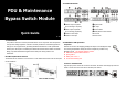
Rack Mount/Wall Mount the Unit
The module can be mounted to a 19” enclosure or wall. Please follow below chart for rack/wall
mount installation.
Chart 1: Rack mounting Chart 2: Wall mounting
2. Product Overview
Master output receptacle
Bypass switch
(for connecting a computer)
AC input
Slave output receptacles
Circuit breaker
(for connecting peripherals)
Master/Slave function switch
Socket to UPS output
δ
Power LED
Socket to UPS input
ε
Slave On LED
3. Installation and Operation
Inspection
Remove the unit from the shipping package and inspect it for damage that may
occur during transportation. Notify the carrier and place of purchase if any
damage is found. The shipping package contains:
Maintenance bypass switch module x 1
Quick guide x 1
Mains power cord x 1
Screws and mounting ears
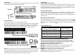
Connect to the Wall Outlet
Plug the input power cord of the unit to the wall outlet. The Power LED will light up when the
mains is normal. The Power LED will be off while power failure.
PDU & Maintenance
Bypass Switch Module
Quick Guide
V. 2.0
Wall