
" User guide
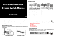

Connect UPS
Connect a power cord from UPS input to UPS input socket on the unit. Use one power cord to
connect UPS output to UPS output socket on the unit.
Connect Equipment
There are two types of output receptacles: Master, and Slave.
To save power consumption, the unit is equipped with Master and Slave output receptacles.
The Master output receptacle will sense if master device (computer) is on. If the master
device is no longer drawing current, it will automatically shut down the power to the Slave
output receptacles. Please refer to below charts for detailed equipment connection.
Switch
NOTE: When the computer is turned off, the Master output receptacle shuts off power to the
slave output receptacles. However, when the computer goes into “sleep mode” or the power
consumption of connected device to Master output receptacle is below 20 W, the Master
output receptacle may not properly recognize the reduced power level.
4. Operation
Transfer to Maintenance Bypass
Before transferring to maintenance bypass, make sure the Power LED is lighting. Transfer
the rotary bypass switch from “Normal” to “Bypass”. At this time, all connected devices are
powered by the utility power directly. You may turn off the UPS and disconnect two cables
connecting to UPS. Then you may now service the UPS.
Transfer to UPS Protection
After maintenance service is done, make sure the UPS operation is normal. Then, reconnect
UPS to the unit by following Installation Section. Verify the Power LED is lighting. Then
transfer the rotary bypass switch from “Bypass” to “Normal”. Now, all connected devices are
protected by UPS.
Master/Slave Function Operation
After connecting all devices to the unit, press “Master/Slave switch” to enable status ( ).
The Slave On LED will light up when connecting load on master output is above 20W. Press
“Master/Slave switch” to disable status ( ), the function is disabled and the Slave On LED
will be on.
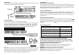
Status & Indicator Table
Status Indicator
1. Utility is normal.
2.
Utility fails but UPS is providing power.
Power LED (Green) on
Utility fails Power LED (Green) off
Master/Slave function is enabled and the
connecting load on master output is above 20W.
Slave On LED (Yellow) on
Master/Slave function is enabled and the
connecting load on master output is below 20W.
Slave On LED (Yellow) off
Master/Slave function is disabled. Slave on LED (Yellow) on
5. Important Safety Warning (SAVE THESE INSTRUCTIONS)
To safely operate this unit, please read and follow all instructions carefully.
Read this manual thoroughly before attempting to unpack, install, or operate.
You may keep this quick guide for further reference.
CAUTION: The product must be used indoor only.
CAUTION: Do not place the unit near liquid or in an excessively damp environment.
CAUTION: Do not place the product directly in the sun or near a hot source.
CAUTION: Do not let liquid or foreign objects enter the product.
CAUTION: Ground the product using a 2P + ground sockets.
CAUTION: When installing the product, ensure that the sum of the leakage currents of the
product and the devices it supplies not exceed 3.5mA.
Plug peripherals into Slave Output Receptacle
Plug computer into Master Output Receptacle
Computer
Monitor
Printer
Online UPS
16A/16A or
16A/10A