TABLE OF CONTENTS 1. INTRODUCTION ················································································1 2. FEATURES ························································································4 3. INSTALLATION ·················································································5 4. PANEL INFORMATION AND OPERATION ······································7 4.1 Panel information ·········································································7 4.
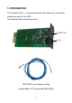
1. Introduction The Remote Panel is a connectivity device that allows you to remotely monitor the status of the UPS. The Remote Panel include three parts: POWER LED RJ45 Remote Card CATEGORY 4 or 5 Network Cable (Length≤400m, DC Resistance≤9.
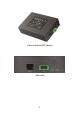
Panel Interface LED Version Side view 2
Power LED: Red LED, when the Power LED is turned on, it shows the power of the remote panel is OK. Signal LED: Green LED, when the Signal LED is flashing, it shows the communication between the UPS and the remote panel is OK, and if the LED is turned on constantly, it shows that the communication is failed. EPO: In emergency case, If the EPO connector be pulled out, UPS will cut off the output emergency.
2. Features The Remote Panel has the following features: ● Real-time monitoring the UPS conditions. ● Can be located away from the UPS with a straight-through CATEGORY 4 or 5 network cable up to 400m. ● Deactivate acoustic alarm. ● EPO (Emergency Power Off) function. ● Hot-swappable function. ● Quick and easy installation and operation.
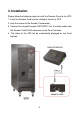
3. Installation Please follow the following steps to install the Remote Panel to the UPS: 1. Insert the Remote Card into the intelligent slot of the UPS. 2. Lock the screws of the Remote Card bracket. 3. Connect the straight-through CATEGORY 4 or 5 network cable from the Remote Card’s RJ45 connector to the Panel Interface. 4. The status of the UPS will be automatically displayed on the Panel Interface.
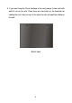
5. If you want hang the Panel Interface to the wall, please fix two nails with width 9 cm on the wall. Since there are two holes on the backside for holding the nails, then you can fix the panel to nails to keep them stable on the wall.
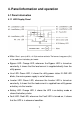
4. Panel information and operation 4.1 Panel information 4.1.1 LED Display Panel ● Mute: Short-press(>0.5s, <4.5s)to mute or activate. The buzzer; Long-press(>5s) in line mode turn into battery test mode. ● Bypass LED: Orange LED, whenever the Bypass LED is turned on constantly, it shows that the load current is supplied directly from the utility power. ● Line LED: Green LED, it shows the utility power status.If LINE LED blinks, the mains power supply is out of tolerance.
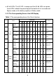
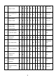
● #2~#6 LEDs: The #2 LED is orange and the #3~#6 LEDs are green, these LEDs indicate the percentage of the load level in Line mode and Bypass mode, or the battery capacity in Battery mode. 4.1.2 The Corresponding Form of the LED Display Table 1. The corresponding form of the Panel Interface. LED display No.
Beep once 11 ↑ Bypass mode ↑ ↑ ↑ ● ● every 2 min, ● ◇ Beep once 12 Overloaded in Line mode ● ● ● ● ● ● ● every sec, ● ◆ Beep once Overloaded in 13 Bypass mode ● ● ● ● ● ● ● every sec, ● ◆ Overloaded in 14 Beep once Battery mode, ● ↑ ↑ ↑ ↑ ↑ ● ● Continuously Overloaded Fault, 15 Cut off the output every sec, ◆ Early-warning ● ↑ ● beep, ◇ Utility power 16 ↑ abnormal ↑ ↑ ↑ ↑ ↑ ★ ↑ ↑ ↑, ◇ Continuously 17 Over temperature ● ● ↑ ↑ beep, ◇ Cont
Continuously 22 BAT SCR failed ● ● ● ↑ ↑ beep, ◇ Beep once 23 Fan abnormal ● ● ● ↑ ↑ ↑ ↑ every sec, ◇ Continuously 24 INV RLY failed ● ● ● ↑ ↑ beep, ◇ Continuously Inner 25 Communication ● ● ↑ ● ↑ beep, ◇ abnormal Continuously 26 Parallel abnormal ● ● ● ● ↑ ↑ beep, ◇ Communication 27 failed between the UPS and the Continuously ★ ★ ★ ★ ★ ★ ★ ★ ★ ★ ● ★ ★ ★ ★ beep, ◇ Remote Panel Beep once 28 EPO function Active every sec, ◇ Continuously 29 Neg
◇ : Alarm can be muted by pressing Mute button. ◆ : Alarm can’t be muted by pressing Mute button. 4.3 EPO Operation EPO Trigger: In emergency case, The UPS can be power off by activation of the EPO function by clearing the shortcircuit between the two pin of the EPO connector or pulling out the EPO connector on right side of the Panel Interface directly, when the EPO function is active, the Panel Interface will display as show in table 1 (NO.28).