CONTENT 1. Product Introduction ......................................................3 1.1 Functions description .................................................................... 3 1.2 Mode description ........................................................................... 4 1.3 Front panel .................................................................................... 5 1.4 Rear panel ..................................................................................... 9 1.
4. Maintenance .................................................................. 26 4.1 Maintenance Safety Instructions................................................. 26 4.2 Typical Trouble Shooting ............................................................. 28 4.3 Battery Maintenance ................................................................... 31 4.4 Contact the service center .......................................................... 31 5. Transport and Storage ...............................
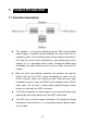
1. Product Introduction 1.1 Functions description This product is a true online double-conversion UPS (Uninterruptible Power Supply). It provides perfect protection for critical load such as computer system. It can eliminate almost all mains power disturbances. The input AC current can be corrected to a wave following the mains voltage, so it is a high power factor system. Through the PWM control technology, the output voltage can be a pure & stable sine wave AC voltage.
1.2 Mode description Bypass mode Bypass mode means that the UPS provides the power through the internal bypass way to load directly without any regulation. If the controller detects the mains is abnormal, it will shut off the output to protect the load. The bypass voltage/frequency range and default output status (on/off) could be set by communication software. Line mode Line mode means that the mains input is rectified/converted by the AC/DC section and then inverted to stable output by DC/AC section.
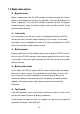
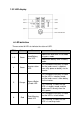
1.3 Front panel 1.3.
1.3.2 LED display LED definition There are total 6 LEDs to indicate the status of UPS. LED No. 1~3 4 5 6 Colour Green Green Orange Red Name Function Load/Battery level LED Inverter status LED Bypass/Batter y mode LED Fault/Warning mode LED -6- Indicate the load level in line mode or bypass mode. Indicate the battery level in battery mode. If it is turned on constantly, it shows that the load current is supplied from utility power or battery via the inverter.
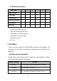
LED action summary LED No. 1 2 3 Bypass mode ○ ○ ○ Line mode ○ ○ ○ ● Battery mode ◎ ◎ ◎ ● ● Battery test mode ◎ ◎ ◎ ● ★ Fault mode ◇ ◇ ◇ ◇ ◇ ● Warning □ □ □ ◇ □ ★ 4 5 6 ★ ○: Lightened according to load level ◎: Lightened according to battery level ◇: Depended on the fault/warning status □: Depended on the original display ●: Lightened constantly ★: Flashing 1.3.3 Button There is only one button for ON/OFF/Mute function on this product.
(2) UPS response to the button Original mode Power off (cold status) Button action UPS response Long-press Turn on the UPS into battery mode. Other press The internal power supply is trigged for a short time and then shutdown. Long-press Turn on the UPS into line mode. Short-press Mute the buzzer if there is a warning or alarming. Long-press Turn into bypass mode. Short-press Turn into battery test mode. Long-press Turn off the UPS. Short-press Mute the buzzer.
1.
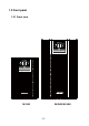
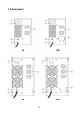
3K / 3KS Communication port (USB or RS232) Mains input protection Mains input power cord Output socket External battery terminal block - 10 -
1.5 Product specification 1.5.1 Model description This manual is applicable to the following models: Model name PowerWalker PowerWalker PowerWalker PowerWalker PowerWalker PowerWalker VFI 1K VFI 1KS VFI 2K VFI 2KS VFI 3K VFI 3KS Power rating 1000VA/700W 2000VA/1400W 3000VA/2100W Note: The model names without “S” represent standard model with internal battery. The model names with “S” represent long backup time model with external battery. 1.5.
1.5.4 Electrical Specification Model name PowerWalker PowerWalker PowerWalker PowerWalker PowerWalker PowerWalker VFI 1K VFI 1KS VFI 2K VFI 2KS VFI 3K VFI 3KS Power 1000VA/700W 2000VA/1400W 3000VA/2100W Input Current (Max.) 5A Voltage Range Frequency Range 6A 10A 11A 15A 16A 176~276VAC @ full load (110~276VAC @ half load) 46 ~ 54Hz @ 50Hz system / 56 ~ 64Hz @ 60Hz system Input Power Factor ≧0.
1.5.5 Standards * Safety IEC/EN 62040-1-1 * EMI Conducted Emission........................:IEC/EN 62040-2 Category C1 Radiated Emission...........................:IEC/EN 62040-2 Category C1 Harmonic Current.............................:IEC/EN 61000-3-2 (Input Current≤16A) Voltage Fluctuation and Flicker........:IEC/EN 61000-3-3 (Input Current≤16A) *EMS ESD.................................................... :IEC/EN 61000-4-2 Level 4 RS.......................................................
2. Installation 2.1 Installation Safety Instructions You must read the following safety instructions before installation! Installation Personnel This product must be installed only by qualified or professional personnel accord to safety instructions! Installation Environment Do not install and operate the UPS when water condensation happen which may occur if the UPS is moved directly from a cold to a warm environment. The UPS must be absolutely dry before being installed and operated.
Wiring & Grounding Installation and Wiring must be performed in accordance with the local electrical laws and regulations. The UPS must be securely grounded. If there are external UPS battery cabinets, please make sure the battery cabinets have the equipotential earth bonding to the UPS main cabinet. An appropriate switch device as backup protection for over-current or short-circuit should be provided in the input utility.
2.3 Installation steps for standard model 1) Make sure the wire / circuit breaker / socket are enough for the current rating of UPS to avoid the hazards of electric shock and fire. 2) Make sure the mains switch in the building is cut off. 3) Make sure the UPS is not be turned on before wiring operation. 4) Turn off all load switches first before connecting the load to the UPS. 5) Make sure the protective earth ground is correct. 6) Connect the loads to the UPS through the outlet sockets.
f) Prepare the external battery cable that should be able to carry the current of >50A, the cross section area should be greater than 5.26 2 mm . It is recommended to use 8 AWG wire or thicker for safety and efficiency. And battery wire color is recommended as following: g) + GND - Red wire Yellow/Green wire Black wire Connect the GND pole of external battery terminal block on the rear panel of UPS to the earth point of battery pack.
3. Operation 3.1 Operation Safety Instructions You must read the following safety instructions before operation! Operation personnel Laymen can operate this product. Operation warning Do not disconnect the earth conducting wire on the UPS or the building wiring terminals in any time since this would cancel the protective earth of the UPS system and all connected loads. Do not try to disassemble the original part of the UPS before turn off and disconnect it from the mains power & external battery.
3.2 Start the UPS with mains (AC source) 1) If the UPS is a long back up time model, with external battery banks, please switch on the battery breaker first; 2) If the wiring is correct, turn on the mains breaker in your building. Then the power supply inside the UPS will be started automatically, the fans will run, and the panel will display with bypass mode.
the UPS will be turned on to the battery mode and output the spec voltage. 3) After the UPS is turned on to battery mode normally, both the Inverter LED and Bypass/Battery LED will be on. The Load/Battery level LEDs will be lightened according to the battery capacity. The buzzer will beep according to the battery level. 3.4 Connect loads to UPS After the UPS is turned on, you can switch on the loads. 1) It is recommended to switch on the load one by one.
3.5 Charge the batteries 1) After the UPS is connected to normal mains, the charger will work and charge the batteries automatically in bypass mode or line mode. 2) Suggest charging the batteries for 10 hours before use. Otherwise the backup time may be less than the standard value. 3.6 Discharge the batteries 1) When the UPS is in battery mode, the buzzer will beep according to different battery level.
automatically periodically. The default period is once per week. 3) The battery test could be performed by the command from monitoring software through the communication port. 4) If the UPS enter the battery test mode, the display and buzzer indication will be same as the battery mode except that the Bypass/Battery LED is flashing. So you can check the battery level at this mode. 3.
3.9 Turn off the UPS with battery (DC) only 1) To turn off the UPS in battery mode, please press the button continuously for more than 2 seconds. 2) After you press the button, the buzzer will beep once. All the LEDs will be lightened, and then black out one by one. Finally all the LEDs will be lightened to indicate the UPS is saving data to the memory. After the saving process, the UPS will be shutdown completely.
3.12 Operation in fault mode 1) In case the Fault/Warning LED is lightened constantly and the buzzer beep continuously, it shows that there is must a fatal error happen to the UPS and it is operating in abnormal mode. 2) If fault happens, please notes and record what the display shows, the display information is very important for the trouble shooing. Please refer to the troubleshooting table in chapter 4 for detail.
3.13 Indication summary in normal operation Operatin g mode Line mode Bypass mode Battery mode Load level Battery level 1 2 3 4 5 6 Buzzer beep once 0~50% ● 50~75% ● ● 75~100% ● ● >100% ★ ★ No output ● ☆ * Every 2 min 0~50% ● ★ Every 2 min 50~75% ● ● ★ Every 2 min 75~100% ● ● ● ★ Every 2 min >100% ★ ★ ★ ★ Every 0.5 sec ● None ● None ● ● None ★ ● Every 0.
4. Maintenance 4.1 Maintenance Safety Instructions You must read the following safety instructions before maintenance! Maintenance Personnel This product must be maintained only by qualified professional personnel accord to safety instructions! Risk of electric shock No matter the UPS is connected to the utility power or not, the output may have electricity. The parts (battery, capacitor) inside the unit may still have hazardous voltage after turning off the UPS.
Remove all jewellery, wristwatches, rings and other metal personal goods before maintenance or repair. Only use tools with insulated grips and handles when maintaining or repairing. Battery Only qualified personnel can replace the batteries! Do not short the positive and negative of the battery electrode. Batteries have a high short-circuit current and may cause a risk of serious shock or fire. When changing batteries, replace with the same quantity and the same type of batteries.
4.2 Typical Trouble Shooting (1) Trouble shooting according to warning indication. LED 1-3 □ □ 4 ★ □ 5 □ □ Possible cause Action Fan abnormal, or Check the fans. Check the loads. internal temperature is Check the ventilation, ambient too high temperature. 6 ★ ★ Check the I/P fuse and related I/P fuse open power component. Check the battery.
(2) Trouble shooting according to fault indication LED 1 2 3 4 ● ● ● ● ● 5 Possible cause Action ● Output short circuit Remove all the loads. Turn off the UPS. Check whether the output of UPS and loads is short circuit. Make sure the short circuit is removed, and the UPS has no internal faults before turning on again. ● Internal fault (inverter failed) Contact the distributor or service center. ● Internal fault (inverter relay short) Contact the distributor or service center.
Note 1: when the UPS failed, the red Fault/Warning LED will be lightened constantly, and the buzzer will beep continuously. Note 2: When the UPS is fault, it will stop the power conversion of mains or battery, the original Load/Battery level LED will code the fault cause. Note 3: If the fault can’t be shoot, please contact the distributor or service center. (3) Trouble shooting in else cases. Problem Battery discharging time diminishes Possible cause Action Battery not yet been fully charged.
4.3 Battery Maintenance 1) The battery used for standard models are valve regulated sealed lead-acid maintenance free battery. It should be charged regularly in order to maximize the expected life of the battery. When being connected to the utility power, whether the UPS is turned on or not, the UPS keeps charging the batteries and also offers the protective function of overcharging and over-discharging. 2) The UPS should be charged once every 4 to 6 months if it has not been used for a long time.
5. Transport and Storage 5.1 Please transport the UPS only in the original packaging. 5.2 The UPS must be stored in the room where it is ventilated and dry.