Online UPS PowerWalker VFI 10000TCP 3/1 PowerWalker VFI 10000TP 3/1 PowerWalker VFI 20000TP 3/1 Manual (EN) Uninterruptible Power Supply System
CONTENT: 1. Safety ........................................................................................................... 1 1.1 Installation............................................................................................... 1 1.2 Operation ................................................................................................ 2 1.3 Maintenance, Servicing and Faults ........................................................ 3 1.4 Transport .............................................
6.2 Converter Function ............................................................................... 40 6.3 Parallel Function ................................................................................... 41 6.4 PowerWalker VFI 10000TCP 3/1 Optional Design of Charger Current 47 6.5 Backfeed Protection ............................................................................. 48 7. Trouble Shooting ...................................................................................... 51 7.
1. Safety Please read carefully the following user manual and the safety instructions before installing the unit or using the unit! 1.1 Installation ★ Condensation may occur if the UPS is moved directly from a cold to a warm environment. The UPS must be absolutely dry before being installed. Please allow an acclimatization time of at least two hours. ★ Do not install the UPS near water or in damp environment. ★ Do not install the UPS where it would be exposed to direct sunlight or near heat.
★ An appropriate disconnect device as short-circuit backup protection should be provided in the building wiring installation. ★ For three-phase equipment connection to an IT power system, a four-pole device which disconnect all phase conductors and the neutral conductor should be provided in the building wiring installation. ★ This is permanently connected equipment, it must be installed by qualified maintenance personnel. ★ Earth connection essential before connecting to the building wiring terminal. 1.
★ Ensure that no liquid or other foreign objects can enter the UPS. 1.3 Maintenance, servicing and faults ★ The UPS operates with hazardous voltages. Repairs should be carried out only by qualified maintenance personnel. ★ Caution - risk of electric shock. Even after the unit is disconnected from the mains power supply (building wiring terminal), components inside the UPS are still connected to the battery which are potentially dangerous.
★ When changing batteries, replace with the same quantity and the same type of batteries. ★ Do not attempt to dispose of batteries by burning them. It could cause explosion. ★ Do not open or destroy batteries. Effluent electrolyte can cause injury to the skin and eyes. It may be toxic. ★ Please replace the fuse only by a fuse of the same type and of the same amperage in order to avoid fire hazards. ★ Do not dismantle the UPS, except the qualified maintenance personnel. 1.
1.6 Standards * Safety IEC/EN 62040-1 * EMI Conducted Emission.................:IEC/EN 62040-2 Category C3 Radiated Emission...................:IEC/EN 62040-2 Category C3 *EMS ESD........................................:IEC/EN 61000-4-2 Level 3 RS..........................................:IEC/EN 61000-4-3 Level 3 EFT.........................................:IEC/EN 61000-4-4 Level 4 SURGE....................................:IEC/EN 61000-4-5 Level 4 Low Frequency Signals.............
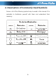
2. Description of Commonly Used Symbols Some or all of the following symbols may be used in this manual.
3. Introduction 3.1 System and model description This Online Series is an uninterruptible power supply incorporating double-conversion technology. It provides perfect protection specifically for computer equipment, communication systems to computerized instruments. Its true online double-conversion design eliminates all mains power disturbances. A rectifier converts the alternating current from the utility power to direct current. This direct current powers the inverter.
High output power factor (0.9), to adapt more type load. Intelligent Battery Management technology that uses advanced battery management to increase battery service life, optimize recharge time. Selectable High Efficiency mode (ECO mode) or CVCF mode operation. Combo input (single phase or three phase) auto detection Back-feed protection Start-on-battery capability for powering up the UPS even if utility power is not available.
PowerWalker VFI 10000 TP 3/1 REAR VIEW PowerWalker VFI 20000 TP 3/1 REAR VIEW 9
Parallel Port (Optional) Intelligent Slot EPO、RS232、USB Fan External Battery AS400 IEC Connector Maintenance and Output Switch Cover Input Breaker Terminal Blocks Cover PowerWalker VFI 10000TCP 3/1 REAR VIEW Fig. 3-1 the rear view of the tower 3-phase series UPS 3.
Current Voltage Output Current 43A MAX 51.8A MAX 200VAC/208VAC/220VAC/230VAC/ 240VAC* 45A/48.1A/45.5A/4 90A/96.2A/90.9A/8 45A/48.1A/45.5A/4 3.5A/41.7A Dimension (WxDxH) mm Net Weight (kg) 86A MAX 7.0A/83.3A 350x650x890 127 3.5A/41.7A 260*550*708 188 85 2) Electrical Performance Input Model PowerWalker VFI 10000TP 3/1 PowerWalker VFI 20000TP 3/1 PowerWalker VFI 10000TCP 3/1 Voltage Frequency Power Factor Three-phase 50/60 Hz±10% >0.
Output Voltage Power Regulation Factor Frequency tolerance. Distortion Current crest ratio Overload capacity 100%-110% load transfers to Bypass mode after 5 minutes ±1% 0.9 lag Synchronized 50/60Hz±10% in Line mode (AC mode) ±0.
4. Installation The system may be installed and wired only by qualified electricians in accordance with applicable safety regulations! 4.1 Unpacking and Inspection 1. Moving to the installation site The tower 3-phase series UPS has wheels making it easy to move the UPS to the installation site after it has been unpacked. However, if the receiving area is far from the installation site, we recommend you to move the UPS by using a pallet jack or a lifter before you start to unpack the UPS. 2.
Remove the packaging following the sequence illustrated in Fig. 4-1 to Fig. 4-4. (only for PowerWalker VFI 10000-20000 TP 3/1) Tools kit Lifter Phillips screwdriver Scissors Wrench Fig. 4-1 Unpacking-step1 Fig.
Fig. 4-3 Unpacking-step3 Fig. 4-4 Unpacking-step4 The shipping materials are recyclable. After unpacking, save them for later use or dispose of them appropriately. 2) Inspect the appearance of the UPS to see if there is any damage during transportation. Do not turn on the unit and notify the carrier and dealer immediately if there is any damage or lacking of some parts.
4.2 Input and Output Power Cords and Protective Earth Ground Installation 1. Notes for installation 1) The UPS must be installed in a location with good ventilation, far away from water, inflammable gas and corrosive agents. 2) Ensure the air vents on the front and rear of the UPS are not blocked. Allow at least 0.5m of space on each side. 3) Condensation to water drops may occur if the UPS is unpacked in a very low temperature environment.
For safety, please cut off the mains power switch before installation. 1) Open the terminal block cover located on the rear panel of the UPS, please refer to the appearance diagram. 2) For tower PowerWalker VFI 10000TCP 3/1 UPS, it is recommended to select the UL1015 8AWG(10mm2) wire or other insulated wire which complies with AWG Standard for the UPS input and output wirings.
8) To connect the load with the UPS, please turn off all the loads first, then perform the connection and finally turn on the loads one by one. 9) No matter the UPS is connected to the utility power or not, the output of the UPS may have electricity. The parts inside the unit may still have hazardous voltage after turning off the UPS. To make the UPS have no output, power off the UPS, and then disconnect the utility power supply. 10) Suggest charging the batteries for 8 hours before use.
PowerWalker VFI 10000TCP 3/1 model Fig. 4-6 Input and output Terminal Block wiring diagram Important notes: If the UPS is used in single mode, JP1 and JP2 must be connected. If the UPS is used in parallel mode, the Jumper between JP1 and JP2 must be removed. Use cable cross section and protective device specification Model PowerWalker VFI PowerWalker VFI 10000TP 3/1 20000TP 3/1 2.5 6 4 10 40A,250VAC 60A,250VAC Min.
External Battery Cabinet Positive Pole(+),Neutral pole,Negative pole(-), Min.conductor cross section[mm2] 10 21 Max.conductor cross section[mm2] 13 25 Line input Backfeed protection A 4-pole disconnection device with device 100A/250VAC, less than 15s break time and min. 1.4mm clearance will be used in final installation for backfeed protection in line input. M2 input Backfeed protection device A 2-pole disconnection device with 100A/250VAC, less than 15s break time and min. 1.
Min.conductor cross section[mm2] 10 Max.conductor cross section[mm2] 13 External Battery Cabinet Positive Pole(+),Neutral pole,Negative pole(-), Min.conductor cross section[mm2] 10 Max.conductor cross section[mm2] 2 Protective Earthing conductor[mm ] Torque for fixing above terminals 13 MAX 13 (10 1b in) Sheet.2 PowerWalker VFI 10000TCP 3/1 model 4.3 Operating Procedure for Connecting with The External Battery 1.
PowerWalker VFI 20000TP 3/1 PowerWalker VFI 10000TP 3/1 Fig. 4-7 Disconnect the internal battery pack DC connectors 2) A DC breaker must be connected between the external battery pack and the UPS. The capacity of breaker must be not less than the data specified in the general specification. 3) Set the external battery pack breaker in “OFF” position and connect the batteries (24 pieces for PowerWalker VFI 10000-20000TP 3/1, 20 pieces for PowerWalker VFI 10000TCP 3/1) in series.
5. Operation 5.1 Display Panel The UPS has a four-button graphical LCD with dual color backlight. Standard back-light is used to light up the display with white text and a blue background. When the UPS has a critical alarm, the backlight changes the text to dark amber and the background to red. Besides the graphical LCD, the UPS has four colorized LEDs to provide you more convenient info. See Figure Below Fig.
Table 5-1 Control Button Functions The Button Function Illustration Power on When the unit is no power and has connected with battery, press this button for >100ms&<1s to power on Turn on When the unit is powered on and in Bypass mode, press this button for >1s to turn on Turn off When the unit has been turned on, press this button for >3s to turn off Enter main menu When displaying default UPS status summary screen, press this button for >1s to enter the main menu tree Exit main menu Press this
Table 5-2 LED definition UPS state Normal LED Battery LED Bypass LED Fault LED (Green) (Yellow) (Yellow) (Red) ★ ↑ ● ↑ △ △ Bypass mode with no output Bypass mode with output Turning on △ Line mode ● Battery mode ● HE mode ● Battery test mode △ △ ↑ ● △ Fault mode Warning ↑ ↑ ↑ ● ↑ △ △ ↑ ● ↑ ★ Note: : ●: △: ★: ↑: Lightened constantly #1-#4 Lightened circularly Flashing Depended on the fault/warning status or other status Table 5-3 Buzzer definition UPS condition Buzze
The UPS provides useful information about UPS itself, load status, events, measurements, identification, and settings through the front panel display. After powering on, the LCD will display the “WELCOME” logo for several seconds and then enter to the default page which shows the UPS status summary. The display automatically returns to the default UPS status summary screen when no button has been pressed within 15 minutes.
5.2 Operating Mode The different graphic symbol could be displayed corresponding to current operating mode or status. Table 5-4 Status Summary Screens Status Summary Screen Description Normal mode: The UPS is operating in Normal mode from utility power. Fig 5-3 Battery mode: When the UPS is running in battery mode, the buzzer beeps once every 4 seconds. Fig 5-4 Bypass with output: The UPS does not have the backup function when it is in bypass mode.
Fig 5-7 High Efficiency Mode: After the UPS is turned on, the power used by the load is supplied from the utility power via internal filter while the utility power is in normal range, so the high efficiency could be gained in the HE mode. Once the mains is loss or abnormal, the UPS would transfer to Line mode or Battery mode and the load is supplied continuously. 1) The function could be enabled through the LCD setting or the software (Winpower, etc.).
Fault: When the fault occurs, it illustrates that some fatal problems happened, the UPS would directly cut off the output or transfer to bypass, and keep alarming. The backlight of Fig 5-10 LCD would also turn to red. Overload: When the UPS is overload, the alarm will beep twice every second. Some unnecessary loads should be get rid of one by one to decrease the loads connected to the UPS.
5.3.1 Turning On UPS With Utility 1) Check that power supply connection is correct. Check the breaker of battery pack is in “ON” position (this step only for long backup time model). 2) For PowerWalker VFI 10000-20000TP 3/1 set input breaker(M1 & M2)in “ON” position, for PowerWalker VFI 10000TCP 3/1 model set input 4P-switch in “ON” position .At this time the fan begins to rotate. LCD will show “WELCOME” logo. Then LCD will show the system status summary screen after UPS finishing self-test.
2) When completing the above action, UPS output voltage is still present. In order to cut off the UPS output, simply cut off the utility power supply. A few seconds later, LCD display shuts down and no output voltage is available from the UPS output terminal. 5.3.4 Turning Off UPS Without Utility 1) button continuously for more To power off the UPS by pressing than 3 second, and the buzzer will beep 3s. The UPS will cut off the output at once.
Fig.
5.4.2 The UPS Status Menu on the menu of “UPS status”, the display would enter By pressing the next UPS status menu tree. The content of UPS status menu tree is same as the default UPS status summary menu. By pressing tree. >1s, the display would return the last main menu The detail information about “UPS status”, please see Fig5-14 5.4.3 The Event Log Menu By pressing on the menu of “Event log”, the display would enter the next event menu tree. All the old event, alarm and fault have been recorded here.
Fig. 5-15 Event menu tree 5.4.4 The Measurement Menu on the menu of “Measurement”, the display would By pressing enter the next measurement menu tree. A lot of detailed useful information could be checked here, Ex. the output voltage and frequency, the output current, the load capacity, the input voltage and frequency, etc. By pressing tree.
Fig. 5-16 Measurement menu tree 5.4.5 The Control Menu By pressing on the menu of “Control”, the display would enter the next control menu tree. 1) Start Battery Test: is one command to control the UPS to do the battery test. 2) Clear EPO status: once EPO status is enabled, the UPS output would be cut off. To recover to normal status, first EPO connector should be opened, and enter this menu to clear EPO status, then UPS would stop alarm and recover to Bypass model.
4) Restore factory settings: all the settings would be recover to default factory settings. It could only be done in Bypass mode. Fig.
5.4.6 The Identification Menu on the menu of “Identification”, the display would enter By press the next identification menu tree. The identification information includes UPS serial number, firmware serial number, model type, would be shown here. By press >1s, the display would return the last main menu tree. Fig. 5-18 Identification menu tree 5.4.7 The Setting Menu Please contact your local distributor for further information before using the settings.
function loss, even directly damage the load, battery or UPS. The most of settings could only be done while UPS is in Bypass mode. Fig.
Example: set rated output voltage value Fig.
6. Special Function The series UPS has some special functions, which could satisfy some special application of user. And the functions have own features, please contact your local distributor for further information before using the function. 6.1 HE Function 6.1.
The great virtue is the output frequency is fixed, which is required by some very sensitive loads. But the load should be derated to 60% when running in converter mode with single phase input, and there is no derating with three phases input. 6.3 Parallel Function 6.3.1 Brief introduction of the redundancy N+X is currently the most reliable power supply structure. N represents the minimum UPS number that the total load needs, X represents the redundant UPS number, i.e.
4) Strictly follow the chapter of 4, the wiring requirement of single UPS to perform the wiring of each UPS. 5) Connect the output wires of each UPS to an output breaker panel. 6) Disconnect the Jumper on JP1 and JP2 of the terminal block first, and connect each output breaker to a main output breaker and then to the loads. 7) Each UPS need an independent battery pack. 8) Please refer to the wiring diagram in the following diagram.
Fig. 6-2 Input and output Terminal Block wiring diagram of PowerWalker VFI 10000-20000 TP 3/1 model Fig.
10) Do not switch on the output breaker of each UPS, switch on the input breaker of the each UPS, the UPS should work in bypass with output, observe their display to check if there are any warning or fault information, measure the output voltage of each UPS separately to check if the voltage difference between them is less than 1V. If the difference is more than 1V, check the wiring. button of one UPS, each UPS would start to turn on, 11) Press the all the UPSs would transfer to the INV mode together.
4) For PowerWalker VFI 10000-20000TP 3/1,Set the main maintenance switch or static switch from “UPS” to “BPS”, For PowerWalker VFI 10000TCP 3/1 model, turn the maintenance switch in the “ON” position, and turn the output switch in the “OFF” position, switch off the main output breaker and the main input breaker, the UPSs would shut down.
maintenance switch of each UPS from “UPS” to “BPS”. For PowerWalker VFI 10000TCP 3/1 model, turn the own maintenance switch in the “ON” position, and turn the own output switch in the “OFF” position. 3) For PowerWalker VFI 10000-20000TP 3/1, Set the main maintenance switch or static switch from “UPS” to “BPS”, switch off the main output breaker and the main input breaker, and the UPSs would shut down.
6.4 PowerWalker VFI 10000TP 3/1 Optional Design of Charger Current 6.4.1 Our charger output current has two optional levels (2A&4A) for different battery pile. 6.4.2 Operate method: 2A charger current method Insert short circuit pin 104-10000-01 in the CN7 position of charger board. This is charging for 7AH*24 pcs or 9AH*24 pcs. 4A charger current method Pull out short circuit pin 104-10000-01 from CN7 position of charger board. This is for 2 piles of 7AH*24 pcs or 2 piles of 9AH*24 pcs.
6.5 Backfeed Protection To support protection against UPS backfeeding a new logic is integrated into PowerWalker VFI 10000-20000TP 3/1 model. But in PowerWalker VFI 10000TCP 3/1 model,there’s no this function. Using backfeed protection On customers side an additional external isolation device (magnetic contactor, MC or minimum voltage tripping device) must be provided as shown in Fig. 6-3. The isolation device must be able to carry the UPS input current (see resp.
Backfeed T.B Mains T.B Terminals Fig. 6-4 PowerWalker VFI 10000-20000 TP 3/1 and external isolation device(in this example a magnetic contactor (MC)) Fig.
Operation If bypass thyristor is short (short circuit) and UPS runs in double conversion mode (online) the following steps follow: The backfeed relay opens and the message “backfeeder” is shown on the LCD panel Reset To reset the backfeed logic the UPS device must be switched Off for some seconds 50
7. Trouble Shooting If the UPS system does not operate correctly, first check the operating information on the LCD display. Please attempt to solve the problem using the table below. If the problem still persists, consult your dealer. 7.
Heatsink Over Temperature Inside temperature of UPS is too high Check the ventilation of UPS and the ambient temperature. The parallel cable is disconnected Check the parallel cable. The parallel cable is disconnected Check the parallel cable. The battery packs of some UPSs are disconnected The M2 bypass input of some UPSs is disconnected Check if all the battery pack is connected.
7.2 Trouble Shooting According To Fault Indication Problem Displayed Inv Overload Fault Possible cause Overload Remedy Check the loads and remove some Alarm code:42 non-critical loads. Check if some loads are failed. Byp Overload Fault Overload Check the loads and remove some Alarm code:43 non-critical loads. Check if some loads are failed. Output Short Circuit Alarm code:31 Output short circuit Remove all the loads. Turn off the UPS. Check if UPS output and loads is short circuit.
Inv Under Voltage UPS internal fault Consult dealer. UPS internal fault Consult dealer. The load is pure inductive and capacitive Remove some non-critical loads. Alarm code:E1 Cable male and female Loss fault The parallel cable is disconnected Check the parallel cable. UPS internal fault Don’t touch any terminal of the equipments which connect one utility power with the UPS even you cut off the utility power. Please Consult dealer.
Emergency supply Batteries not fully Charge the batteries for at least 12 period shorter than charged / batteries hours and then check capacity. nominal value defect Please have the following information at hand before calling the After-Sales Service Department: 1. Model number, serial number 2. Date on which the problem occurred 3. LCD/LED display information, Buzzer alarm status 4. Utility power condition, load type and capacity, environment temperature, ventilation condition 5.
8. Battery Maintenance, Replacement and Disposal 8.1 Maintenance ■ This series UPS only requires minimal maintenance. The battery used for standard models are value regulated sealed lead-acid maintenance free battery. These models require minimal repairs. The only requirement is to charge the UPS regularly in order to maximize the expected life of the battery.
8.2 Replacement and Disposal of Batteries 1) Before disposing of batteries, remove conductive jewelry such as necklace, wrist watches and rings. 2) If it is necessary to replace any connection cables, please purchase the original materials from the authorized distributors or service centers, so as to avoid overheat or spark resulting in fire due to insufficient capacity. 3) Do not dispose of batteries or battery packs in a fire, they may explode.
Open the front panel and request service engineer to replace batteries. Steps: 1) Remove the front panel and disconnect the connector on the LCD display board. See Fig. 8-1. Fig. 8-1 Easy for Battery Replacement -Step 1 2) Disconnect the battery pack DC connectors and remove the battery fixed plate. See Fig. 8-2. battery fixed plate Fig.
3) Remove the battery pack from the cabinet. See Fig. 8-3. Fig. 8-3 Easy for Battery Replacement -Step 3 4) Replace the old battery packs with the new ones. 5) Reconnect the DC cables. Note: The battery pack is 20kg weight, be careful not to fall off when you operate the battery replacement. If you want to replace batteries without powering down the UPS, you need to set the UPS work in Bypass Mode.
9. Communication Port 9.1 RS232&USB Interface RS232&USB interface is for the monitoring software and firmware update. There is only one option can work in the same time and same product. 1) The following is the pin assignment and description of DB-9 connector. Pin # Description I/O 2 TXD Output 3 RXD Input 5 GND Input 2) The USB port is compliance with USB 1.1 protocol for its communication software. 9.
Pin # Description I/O Pin # Description I/O 1 UPS Fail Output 6 Bypass Output 2 Summary Alarm Output 7 Battery Low Output 3 GND Input 8 UPS ON Output 4 Remote Shutdown Input 9 Line Loss Output 5 Common Input Fig.
10. Software Installation WinPower is UPS monitoring software, featuring user-friendly interface to monitor and control your UPS. This unique software provides complete power protection for computer system while power failure. With the software users can monitor any UPS status on the same LAN.
63