
Owner manual


19
PowerWalker VFI 10000TCP 3/1 model
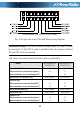
Fig. 4-6 Input and output Terminal Block wiring diagram
Important notes: If the UPS is used in single mode, JP1 and JP2 must
be connected. If the UPS is used in parallel mode, the Jumper between
JP1 and JP2 must be removed.
Use cable cross section and protective device specification
Model PowerWalker VFI
10000TP 3/1
PowerWalker VFI
20000TP 3/1
Input L1,L2,L3
Min.conductor cross section[mm
2
]
Max.conductor cross section[mm
2
]
2.5
4
6
10
Input L1,L2,L3 breaker (A) 40A,250VAC 60A,250VAC
Input N, M2
Min.conductor cross section[mm
2
]
Max.conductor cross section[mm
2
]
10
13
21
25
Input M2 breaker (A) 63A,250VAC 100A,250VAC
Input fuse (A) 30A,250VAC 50A,690AC
Output L,N,
Min.conductor cross section[mm
2
]
Max.conductor cross section[mm
2
]
10
13
21
25