Online UPS PowerWalker VFI 1000T LCD PowerWalker VFI 2000T LCD PowerWalker VFI 3000T LCD Manual (EN) Uninterruptible Power Supply System -1-
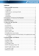
CONTENT 1. Safety and EMC Instructions .............................................................. 1 1.1 Installation......................................................................................... 1 1.2 Operation .......................................................................................... 2 1.3 Maintenance, servicing and faults .................................................... 3 1.4 Transport.......................................................................................
7. Setting by LCD Module ...................................................................... 24 8. Trouble Shooting ................................................................................ 27 9. Maintenance........................................................................................ 31 9.1 Operation ........................................................................................ 31 9.2 Storage .....................................................................................
1. Safety and EMC Instructions Please read carefully the following user manual and the safety instructions before installing the unit or using the unit! 1.1 Installation ★ See installation instructions before connecting to the supply. ★ Condensation may occur if the UPS is moved directly from a cold to a warm environment. The UPS must be absolutely dry before being installed. Please allow an acclimatization time of at least two hours. ★ Do not install the UPS near water or in damp environment.
★ UPS has provided earthed terminal, in the final installed system configuration, equipotential earth bonding to the external UPS battery cabinets. ★ An appropriate disconnect device as short-circuit backup protection should be provided in the building wiring installation. Please see the disconnect device specification in chapter 5.2. ★ Equipment the powered more than one source. 1.
★ Ensure that no liquid or other foreign objects can enter the UPS. ★ Do not remove the enclosure. This system is to be serviced by qualified service personnel only. ★ Remove the protective panel only after disconnecting the terminal connections. ★ Use No. 12AWG (for 3K/KS output terminal), 90℃ copper wire and 12 lb-in Torque force when connecting to terminal block. ★ Use No. 12 AWG (for 3KS input wire), 90℃ copper wire and 4.4 lb-in Torque force when connecting to terminal block. 1.
- use only tools with insulated grips and handles. ★ When changing batteries, replace with the same quantity and the same type of batteries. ★ Do not attempt to dispose of batteries by burning them. It could cause explosion. ★ Do not open or destroy batteries. Effluent electrolyte can cause injury to the skin and eyes. It may be toxic. ★ Please replace the fuse only by a fuse of the same type and of the same amperage in order to avoid fire hazards.
1.6 Standards * Safety IEC/EN 62040-1 * EMI Conducted Emission................................:IEC/EN 62040-2 Category C1 Radiated Emission...................................:IEC/EN 62040-2 Category C1 Harmonic Current.................................:IEC/EN 61000-3-2 Voltage Fluctuation and Flicker............:IEC/EN 61000-3-3 *EMS ESD......................................................:IEC/EN 61000-4-2 Level 4 RS.........................................................
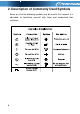
2. Description of Commonly Used Symbols Some or all of the following symbols may be used in this manual.
3. Introduction This On-Line-Series is an uninterruptible power supply incorporating double-converter technology. It provides perfect protection specifically for Novell, Windows NT and UNIX servers. The double-converter principle eliminates all mains power disturbances. A rectifier converts the alternating current from the socket outlet to direct current. This direct current charges the batteries and powers the inverter.
4. Panel Description The Display Panel Switch ON-Button OFF-Button Select-Button Enter-Button 8 Function Turn on UPS system: By pressing the ON-Button “I” the UPS system is turned on. Deactivate acoustic alarm: By pressing this Button an acoustic alarm can be deactivated in the battery mode. Do the battery test: By pressing this Button the UPS can do the battery test in the Line mode or ECO mode or Converter mode.
The LCD Display Display Function Input Information Indicates the input Line voltage value, which could be displayed from 0 to 999Vac Indicates the frequency value of input Line voltage, which could be displayed from 0 to 99Hz Indicates the input Line voltage is higher than the SPEC range, and the UPS would be working in Battery mode Indicates the input Line voltage is lower than the SPEC range, and the UPS would be working in Battery mode Output Information Indicates the UPS output voltage value, which c
Indicates the load is over the SPEC range Battery Information (1) Indicates the battery voltage value, which could be displayed from 0 to 999Vdc Indicates the battery capacitance percent, which could be displayed from 0 to 199% Indicates the battery is over charged, and the UPS would be switched to Battery mode Indicates the battery is weak, and the UPS would shut down soon Mode/Fault/Warning code Information Indicates the operating mode of the UPS, Mode code or Fault code or Warning code could be displa
(1) Here would become , , does operating mode of UPS setting. instead when the user “UPS” means the setting of normal inverter mode (Line mode). “ECO” means the setting of economy mode. “CVF” means the setting of converter mode. The detail illustration of the three modes and the operation of the setting would be presented in the following section.
5. Connection and Operation The system may be installed and wired only by qualified electricians in accordance with applicable safety regulations! When installing the electrical wiring, please note the nominal amperage of your incoming feeder. 5.1 Inspection: Inspect the packaging carton and its contents for damage. Please inform the transport agency immediately should you find signs of damage. Please keep the packaging in a safe place for future use.
When selecting the NFB, the user can refer to below table for detailed information when installation. UPS INPUT NFB Model No. VOLTAGE CURRENT PowerWalker VFI 1000T LCD (L) 300Vac 10A PowerWalker VFI 2000T LCD (L) 300Vac 20A PowerWalker VFI 3000T LCD (L) 300Vac 32A (2) UPS Output Connection The output of the UPS is IEC socket-types. Simply plug the load power cord to the output sockets to complete connection. Use one cord for every 5A load. Model No.
(3) EPO Connection: User can select the polarity of EPO, EPO is Normally open as default setting. ● Normally open Normally the EPO connector is open on the rear panel. Once the connector is closed with a wire, the UPS would stop the output until the EPO status is disabled. Disable the EPO status Enable the EPO status ● Normally close Normally the EPO connector is closed with a wire on the rear panel.
5.4 Turn on the UPS: (1) With utility power connecting: Press “I” button continuously for more than 1 second to turn on the UPS, the UPS will get into the inverter mode, the LCD screen will indicate the state of the UPS.
5.7 Audible alarm mute function: If the alarm is too annoying in battery mode, you may press “I” button continuously for more than 1 second to clear it. Moreover, the alarm will be enabled when the battery is low to remind you to shutdown the load soon. If the alarm is too annoying in bypass mode, you may press “ “button continuously for more than 1 second to clear it. The action doesn’t affect the warning and fault alarm. 5.
(6) The red wire is connected to the "+" terminal of the battery. The black wire is connected to the "-" terminal of the battery. (Note: the green/yellow wire is grounded for protection purpose.) (7) Make sure the wires are fasten, install the terminal block cover on the rear panel of the UPS. (8) Connect the UPS to the load. Then, turn on the mains switch or connect the power cord of the UPS to utility power supply, the battery would start to be charged.
6. Operating Mode for All Models The different codes could be displayed on the LCD screen corresponding to their own operating modes, and they are illustrated as the following table. At any time, only one normal operating mode or fault mode is presented. But the warning, even several warnings could appear in a certain normal operating mode at one time. And the normal operating mode code and the warning code would be shown circularly.
■ The Line mode If output overloaded, the load percent is shown and alarm will keep twice every second. You should get rid of some unnecessary loads one by one to decrease the loads connected to the UPS less than 90% of its nominal power capacity. Note: Please follow the following steps to connect the generator: ● ● Activate the generator and wait until the operation is stable before supplying power of the generator to the UPS (be sure that the UPS is in idle mode).
(1) When the UPS is running in battery mode, the buzzer beeps once every 4 seconds. If the “ON” button on the front panel is pressed for more than 1 second again, the buzzer will stop beeping (in silence mode). Press the “ON” button once again for more than 1 second to resume the alarm function.
■ The Bypass mode The UPS does not have the backup function when it is in bypass mode. The power used by the load is supplied from the utility power via internal filter. 6.4 NO output mode The LCD display in No output mode is shown in the following diagram. The information about the utility power, the battery, the UPS output and the load could be displayed. The “0” code indicates the UPS is working in the No output mode.
6.5 EPO (Emergency Power Off) It is also called RPO (Remote Power Off). On LCD display, the mode code is “0”, the word of “EPO” are presented in the position of output voltage. It is a special status in which the UPS would shut the output off and alarm. The UPS could not be turned off by pressing “OFF” button on the panel, only after releasing EPO status by turning off the EPO switch. 6.6 ECO mode (Economy mode) It is also called high efficiency mode. In ECO mode, on LCD display, the mode code is “5”.
2) The load should be derating to 60% in converter mode. 6.8 Abnormal mode In abnormal mode such as Bus fault etc., the corresponding fault code would be shown to indicate the operating mode of the UPS. And some warning words could also be shown, for example “short!” would be shown when the load or the UPS output is short and the UPS is in inverter fault mode.
7. Setting by LCD Module The output voltage and frequency, and bypass state, and ECO mode, and Converter mode could be set directly through LCD module. The output voltage could be set to 208V, 220V, 230V and 240V. The output frequency could be set to 50Hz and 60Hz. The operating mode of UPS could be set between the Line mode, ECO mode and Converter mode. The bypass state could be set to enable and disable. But all the settings could only be done when the UPS is in bypass or no output mode.
■ Here is a example for changing the output voltage from 220Vac to 230Vac through the LCD panel. Step 1: One flickering black dot would appear before “208Vac” after pressing the “Select” button. Step 2: The flickering dot would move to “230Vac” after pressing the “Select” button two times again.
Step 3: The dot before “230Vac” would turn to flickerless after pressing the “Enter” button. Step 4: The output voltage would be 230Vac after the UPS is turned on.
8. Trouble Shooting If the UPS system does not operate correctly, check the operating status on the LCD display.
Fault Code Bus fault 05 Inverter fault 06 Overload fault 07 Over temperature fault 08 Inverter short 14 Bus short 28 If the UPS system does not operate correctly, please attempt to solve the problem using the table below.
Fan fail Fan abnormal Check if the fan is running Battery over voltage Battery is over charged Battery low Battery voltage is low Charge fail The charge is broken Inside temperature of the UPS is too high Inside temperature of the UPS is too high The ambient temperature is too high Input power voltage is too high Switching to battery mode automatically, and after the battery voltage is normal and the mains is normal, the UPS would Switching to line mode automatically again.
system. Bus fault of UPS system are reversed EPO function is enabled UPS internal fault Inverter fault UPS internal fault Notify dealer Over temperature fault Over temperature Inverter short Output short circuit Bus short UPS internal fault Check the ventilation of the UPS, check the ambient temperature and ventilation. Remove all the loads. Turn off the UPS. Check whether the output of UPS and loads is short circuit.
9. Maintenance 9.1 Operation The UPS system contains no user-serviceable parts. If the battery service life (3~5 years at 25°C ambient temperature) has been exceeded, the batteries must be replaced. In this case please contact your dealer. 9.2 Storage If the batteries are stored in temperate climatic zones, they should be charged every three months for 1~2 hours. You should shorten the charging intervals to two months at locations subject to high temperatures. 9.
10. Technical Data 10.1 Electrical specifications Phase INPUT PowerWalker PowerWalker PowerWalker VFI 1000T LCD VFI 2000T LCD VFI 3000T LCD (L) (L) (L) Single Frequency (45~55)/(54~66) Hz Model No. Current(A) 9A 17A 26A OUTPUT PowerWalker PowerWalker PowerWalker VFI 1000T LCD VFI 2000T LCD VFI 3000T LCD (L) (L) (L) Power rating 1kVA/0.8kW 2kVA/1.6kW 3kVA/2.4kW Model No. Voltage 200/208/220/230/240×(1 士 2%)VAC Frequency 50/60±0.
10.2 Operating Environment Ambient Temperature 0 oC to 45 oC Operating humidity < 95% Altitude < 1000m Storage temperature 0 oC to 45 oC 10.3 Typical backup time (Typical values at 25°C in minutes:) Model No. 100 % Load 50 % Load PowerWalker VFI 1000T LCD 5 14 PowerWalker VFI 2000T LCD 9 21 PowerWalker VFI 3000T LCD 5 15 10.4 Dimensions and weights Model No.
11. Communication Port The communication port is for the monitoring software. A USB port and an intelligent slot are provided. 11.1 USB The USB port is compliance with USB 1.1 protocol. 11.2 RS232 Interface(Option) The following is the pin assignment and description of DB-9 connector. Pin # 2 Description TXD I/O Output 3 5 RXD GND Input Input 11.
DB-9 Interface of AS400 communication protocol 35
12. Software Installation WinPower is UPS monitoring software, featuring user-friendly interface to monitor and control your UPS. This unique software provides complete power protection for computer system while power failure. With the software users can monitor any UPS status on the same LAN.
Appendix: Rear panel PowerWalker VFI 1000T LCD PowerWalker VFI 1000T LCD L 37
PowerWalker VFI 2000T LCD PowerWalker VFI 2000T LCD L 38
PowerWalker VFI 3000T LCD PowerWalker VFI 3000T LCD L 39
61440