PowerWalker VFI 3/3 Series VFI 20000TP 3/3 BE/BI 380/400/415V 50/60Hz (3-phase input/output) User Guide
EN ©2013 BlueWalker GmbH All Rights Reserved The contents of this manual are the copyright of the publisher and may not be reproduced (even extracts) unless permission granted. Every care has been taken to ensure the accuracy of the information contained in this manual, but no liability can be accepted for any errors or omission. The right to make design modifications is reserved.
User Guide UPS 20kVA B, 380/400/415V, 50/60 Hz (3-phase input/3-phase output) 614-09943-02 Contents 1. Safety instructions….....……………………………………………………....……….. 01 1.1 Safety caution….....………………….....………………….....…………………..... 01 1.2 Audience caution….....………………….....………………….....……………… 01 1.3 CE marking….....………………….....………………….....………………….....… 02 1.4 User precaution….....………………….....………………….....………………02 1.5 Environment….....………………….....………………….....…………………..... 03 1.6 Inquiries….....………………….....………………….....
21 5. Electrical installation…………………………………..............……………………… 5.1 Electrical Preparations…………………………………………………………… 21 21 5.2 Installation and wire connection diagram……………………………………… 24 5.3 Suggested cable and protective devices……………………………………… 5.4 Internal Battery Installation……………………………………………………26 5.5 Connecting the external battery………………………………………………29 30 5.6 Connections between battery cabinet and UPS……………………………… 5.7 Handling the batteries…………………………………………………………… 31 6.
1 Safety instructions This user manual contains important safety instructions and operating instructions. Please read the user manual carefully before operating or working on the UPS and save it for reference in the future. 1.1 Safety caution The UPS operates with external AC mains, battery cabinet(s) or bypass power. It contains components that carry hazardous voltages and high currents, The properly installed enclosure is earthed and IP20 rated against electrical shock and foreign objects.
Caution! Read the manual before operating or working on the UPS. EN 1.3 CE marking The product has the CE marking in compliance with the following European directives: LVD Directive (Safety) 2006/95/EEC EMC Directive 2004/108/EEC Note! This product for commercial and industrial application in the second environment Installation restrictions or additional Measures may be needed to prevent disturbances. 1.
1.5 Environment The UPS must be installed according to the recommendations in this manual.Under no circumstances the UPS should be installed in an airtight room, in the presence of flammable gases, or in an environment exceeding the specification.Excessive amount of dust in the operating environment of UPS may cause damage or lead to malfunction. The UPS should be always protected from the outside weather and sunshine. The recommended operating temperature is from +15 to +20 Celsius degrees.
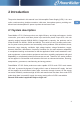
2 Introduction The product described in this manual is an Uninterruptible Power Supply (UPS). It is a true online, continuous duty, double conversion, solid state, three-phase system, providing conditioned and uninterruptible AC power to protect the end-user's load. 2.1 System description PowerWalker VFI 3/3 Series products are high-efficiency and high-performance, double conversion, pure-online and three phase input and three phase output UPS, with unit capacity ranging between 20KVA-40KVA.
2.2 Basic system configuration 2.
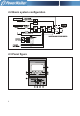
① AC: This light and inverter light will turn "green" when UPS is powered by Rectifier Input; ② Inverter: This light will turn "green" when UPS load is through the inverter; ③ Battery: This light will turn "yellow" when UPS is powered by batteries; ④ Bypass: This light will turn "green" when UPS load is powered by Bypass Input; ⑤ Fault: If the UPS worked under fault condition,this light would turn on and stay “red” with continuous warning tone being given off in case of UPS abnormal function;or flash “red”
CHGR FAN Battery trays Front view(door open) 7
3 Technical data 3.1 Standards EN UPS VFI 20000TP 3/3 BE/BI Safety IEC62040-1:2008,EN62040-1:2003 and EN60950-1:2005 EMC IEC62040-2:2006 and EN62040-2:2005 Product IEC62040-3:1999 and EN62040-3:2001 3.
3.4 Characteristics VFI 20000TP 3/3 BE/BI Efficiency-nominal load Up to 92% Noise (ISO 7779) <57dB at 75% load 3.5 AC input VFI 20000TP 3/3 BE/BI Rectifier input 3 phases + N Bypass input 3 phases + N Voltage (L-N) 121V-274 Volts without using battery Frequency 40-70 Hz Power factor 0.99 Input distortion < 5% THD(I) Rated input voltage 380V/400 V/415V Rated input current 29A/28A/27A 3.
3.7 AC output VFI 20000TP 3/3 BE/BI Active power 16KW Number of phases 3-phases + N Frequency 50/60HZ Voltage (L-N) Overload capability (Mains available) Overload capability (battery available) EN 220/230/240 VAC 110%150% 0.
4 Mechanical installation The UPS and accessories are delivered on a specifically designed pallet that is easy to move with a forklift or a pallet jack. Keep the UPS always in upright position and do not drop the equipment. Do not stack the pallets. 4.1 Delivery check The UPS is delivered with the following items: 1. Winpower disc 2.RS-232 serial cable 3.User Guide 4.Key 5.Battery kit(wires & trays)(only for models without batteries) 4.
EN Check the information on the type designation label of the equipment to verify that the unit is of the correct type. The type designation label includes ratings, a CE marking, a type code, a part number and a serial number. The serial number is important when making inquiries. It allows individual recognition of the equipment.
4.3 Planning before installation The equipment must be installed in upright position. The equipment requires space to front and back to enable cooling airflow. Service and maintenance require more than 40cm clearance on right hand side. All cooling air enters at front and exits at unit rear. The required minimum clearance from unit rear to an obstruction is 50cm. Because the service and user access is in the front there should be reserved enough space (min 60cm). Preparation for installation. 1.
4.4 Cabinet installation The required distance for UPS units should allow for service access. The same applies to the battery cabinet(s) that should be installed next to the UPS cabinet(s). EN Caution! UPS cabinet(s) can fall over if the installation brake pads are not used. Both rear and front pads must be used to secure the UPS cabinet to the floor. Use a 19mm wrench in clockwise direction to screw the brake pad down to the ground, keeping the machine from moving. 4.
The switching sequence for circuit breaker from normal position to maintenance position: The normal positions of the MBS switches.
The maintenance positions of the MBS switches EN Transfer UPS from normal mode to maintenance bypass mode: 1.The normal start position should be following: 2.
1)Switch-off picture 2)If it is in single machine mode, the following will appear Remember to verify the transfer before proceeding the next step. 3.Remove the locking plate of maintenance switch. 4.Turn OFF the Rectifier Input switch and battery fuse. 5.Turn the Maintenance switch to “MAINTENANCE” side. 6.Turn OFF the Bypass Input switch and N switch.
7.UPS is now in the maintenance bypass mode, see below (Note: the Serv disconnect i.e. battery fuse must be turned off): EN Transfer UPS from maintenance bypass mode to normal mode: 1.The normal start position should be following: 2.Turn ON the Bypass Input switch and N switch When the LED of bypass turns green,the UPS enters into bypass mode. 3.Turn the Maintenance switch to “UPS” side.
Then the UPS turn to bypass mode. 4.Turn ON the Rectifier Input switch and battery fuse. 5.
6.UPS is now in the normal mode,see below: EN 7.Remount the locking plate of maintenance switch to the position to prevent the use of it.
5 Electrical installation 5.1 Electrical Preparations Note! It must be ensured that no line input source can accidentally be connected to the UPS during installation. Warning! Installation may only be carried out by qualified technicians and in conformity with the applicable safety standards. Warning! The UPS unit is not applicable to the IT power distribution system. 5.
24 black wires with an approximate length of 8 cm and 2 black wires with an approximate length of 30 cm for BAT-. 7 black wires for BAT- connection between Shelf 4 and Shelf 5. 1.If UPS rectifier input and bypass input are supplied from two mains: Connect the mains 1 supply cables to the UPS rectifier input terminals L1, L2, L3, N and PE. Connect the mains 2 supply cables to the UPS bypass input terminals L1, L2, L3, N and PE.
2.If UPS rectifier input and bypass input are supplied from one mains only: Connect the mains supply cables to the UPS rectifier input terminals L1, L2, L3, N and PE . The following three jumpers must be fixed between the rectifier and bypass input terminals: L1-L1, L2- L 2, L3- L3. Terminal block diagram Warning! High touch current earth connection essential 23 before connecting supply.
In order to gain access to the external electrical connections it is necessary to remove the front terminal protective panel of the UPS. Before the cables are connected they shall be passed through the cable glands to hold them in position and tightened. Connect the Protective Earthing (PE) cable first. Connect other cables as shown in the connection terminal representations on the preceding and following pages. Ensure that the UPS is isolated before removing front terminal protective panel. 5.
Use cable cross section and protective device specification Model Rectifier Input L1, L2, L3, N, Bypass Input L1, L2, L3, N, min. conductor cross section[mm 2] max. possible cross section[mm 2] Rectifier Input L1, L2, L3, N breaker (A) VFI 20000TP 3/3 BE/BI 6 35 60A 230VAC Bypass Input L1, L2, L3, breaker (A) 60A 230VAC Rectifier Input fuse (A) 60A 250VAC Bypass Input fuse (A) 60A 250VAC Internal battery fuse 100A 700VAC Output L1, L2, L3, N, min. conductor cross section[mm 2] max.
Warning! ENSURE THAT THE UNINTERRUPTIBLE POWER SYSTEM IS ISOLATED BEFORE WORKING ON THIS CIRCUIT. EN 5.4 Internal Battery Installation REMARK: THE FOLLOWING WARNINGS SHOULD BE OBSERVED DURING THE OPERATION: -The batteries may contain potential electric shock danger because of high voltage. -Wear safety goggles. -Make sure to verify battery polarity before connecting. -Make sure to keep wires away from the adjacent legs and sharp edges of shelves handles.
4. Connect the cables to each shelf respectively (see Fig. 2). Remark: make sure the cables between the shelves are disconnected and the following wire connections are done: B1, B2, B3, B4, B5, B8, B9, B10, B11, B12, B15, B16 and other 24 black cables without labels. Fig. 2 5. Pack the battery trays and put them into the enclosure (see Fig. 1 & Fig. 2). 6. Secure each tray with two screws. 7. Connect the cables between shelves and other two cables (B13 and B14).
Table1: Battery cable list Label Colour B1 B2 B3 B4 B5 No label B8 B9 B10 B11 B12 B13 B14 B15 B16 Blk Blu Red Blk Blk Red Red Blk Blk Red 24 24 1 Length(mm) 120 230 400 420 80 80 500 130 130 300 300 350 150 200 200 Quantity Red Blk Red Blk Red 2 3 2 1 1 1 2 2 1 1 1 1 Fig.
5.5 Connecting the external battery Before connecting the external battery, please read the notice and warning label on the UPS. Warning! In the event of malfunction, the battery cabinet chassis or battery cabinet frames may become live! Warning! Special care should be taken when working with the battery cabinet associated with the PowerWalker VFI 3/3 Series 20 - 40 kVA. When the battery cabinet is connected the overall voltage exceeds 400V.
Notice! The requirements of the EC directives are satisfied when battery cabinet are used with original accessories. If alternative batteries are used, you must ensure that the applicable EC directives are met and declare conformity. EN Connect the battery cabinet as follows: Turn off the UPS. Check all the three internal battery fuses are not inserted and/or any external battery switchs open. Connect PE first.
5.7 Handling the batteries Warning! Batteries are a potential source of danger due to their electrical charge and chemical composition. Therefore observe the battery handling instructions of the manufacturer. These usually can be found in the material which accompanies the shipment. Recharging batteries Warning! When recharging, observe the indications on the packaging. Exchanging batteries Warning! Before replacing batteries, make sure that those to be installed are fully charged.
6 Software and connectivity The Series provide Intelligent Slot, Expanded Slot, PARALLEL, AS400, EPO, RS485 and RS232 as well as SERVICE Supervising Communication Interface exclusively available to PowerWalker technical personnel. 1 3 PARALLEL 4 PARALLEL AS400 5 EPO 7 RS485 Intelligent slot SERVICE RS232 Expanded slot 2 6 8 1. Intelligent slot: suitable for WebPower card of remote supervising management,enabling you to realize remote supervising management on UPS through Internet. 2.
RS232 port RS485 port 33
AS400 port EN Note! The UPS have to be manually reset if remote shutdown occurs.
7 User operations Warning! High touch current earth connection essential before connecting supply. The only user operations permitted are: Start up and shut down the UPS, excluding the commissioning start-up. Use of the LCD control panel and Emergency Power Off (EPO) switch. Use of optional connectivity modules and their software. Warning! The user must follow the precaution, warnings and only perform the described operation.
Remark: the following drawing takes PowerWalker VFI 20000TP 3/3 as an example and statistics are only for reference.
5)Press ▼ again to obtain the below 6)Press ▼ again to obtain the below information information 7)Press ▼ again to obtain the below 8)Press ▼ again to obtain the below information information VFI 20000TP 3/3 37
Note! If malfunction occurs, “x” will appear at the lower right corner of the display,while a warning occurs, “ ” will appear at the same position (as illustrated in the below picture with battery mode as an example). EN 4.
3)Select “Yes, Confirm” to switch on 4)Normal Switch-on the machine 5)Battery power supply (switch off line input switch) 39
5.
5)Select “Yes, Confirm” to switch off 6)Normal Switch-off the machine Note! If you intend to switch off only one set of UPS among the parallel machine system, select “single machine switch-off”; if switch-off is intended for the entire parallel machine system, select “parallel machine switch-off”. 6.
7. Configuration (press ESC to exit the above picture) You are able to access Setting picture by using user combination (default: 1234, subject to personal modification) so as to set the following programs. 1)Action display (bypass power supply) 2) Press ▼ 3)Enter respective password 4)Select action item EN 8. The Series is capable of DC start-up without AC input, panel display being similar to switch-on picture with AC supply.
9. Procedures of DC switch-on: Activate DC switch-on function set under UPS bypass mode Make sure that “+”, “-” and “N” wires of batteries are properly connected to UPS Switch on batteries Lightly touch ENTER Manually conduct switch-on order within about 1min after LCD self-inspection Note! UPS will be switched off automatically if there is no operation within 1min after LCD self -inspection is completed! 7.
Parallel machine wire connection drawing(one battery supply) EN Parallel machine wire connection drawing(separate battery supply) 44
Single machine wire connection drawing 45
8 Maintenance Warning! EN The Maintenance must be performed by a service engineer form the manufacturer or form an agent authorised by the manufacturer. PowerWalker VFI 20000TP 3/3 requires minimum maintenance. 1. If battery is switched off, loaded equipments will not be covered for power-off protection. 2. Make sure UPS vent are properly ventilated and clean side frames and fan vents from dusts every half a year (switch off AC, battery cabinet and internal battery fuse prior to cleaning) 8.
Remark: A. Prior to battery replacement, switch off UPS and remove it from AC and battery, take off internal battery fuse. B. Take off metallic articles such as rings and watches. C. Use screw drivers equipped with insulated handles and do not place tools or other metallic substances on the batteries. D. Short circuit or reverse connection is forbidden for battery polarity connection. The troubleshooting procedure gives simple remedial if a malfunction occurs in the UPS.
8.2 Regular service/intervals The UPS requires very little maintenance if installed in an appropriate environment. In order to ensure maximum availability of the UPS, manufacturer recommends signing a proactive service agreement with a local authorised service provider. Maintenance Batteries change Batteries test Cooling fan change Interval 3-5 years or according to battery suppliers recommendations 18 months 5 years 8.3 Cooling fan The cooling fan lifespan of the UPS unit is about 60 000 operating hours.
9 Parallel systems Note! Parallel is only connected to identical ports for the UPS of same models and kVA rating. 1) Follow installation instructions for general installation requirements. 2)Ventilation spacing between machines should allow for service access. 3) Input wiring for each set of UPS should follow the requirements for that of single unit. Each UPS input should be connected to the same input patch board.
EN Note! Parallel signal cable should be connected as a loop.
10 Recycling the used UPS or battery Before scrapping UPS or its battery cabinet, the battery bank must be removed. Local requirements must be followed in battery recycling or discard. The removal of batteries is allowed only by authorised service personnel due to high energy and voltage. Do not discard waste electrical or electronic equipment in the trash. For proper disposal, contact your local collecting/recycling/reuse or hazardous waste center and follow the local legislation.
11 Display reference Table EN 52
Should any display or warning message excluded in the above table be found,please contact distributor or call PowerWalker Hot line for advice. ● Indicator light is on ★ Indicator light flashes Warning include one or more than one of these: 1.EPO active 11.Charger failure 2.Line loss 12.Battery over restrict 3.Neutral loss 13.Battery over temperature 4.Line phase error 14.Fan over restrict 5.Bypass loss 15.BUS capacitor over restrict 6.Bypass phase error 16.Fan failure 7.Battery open 17.Fan disconnected 8.
614-01718-00