Thanks for your purchasing this product! Safety instruction Please read carefully the safety instructions before you do anything to this product!
CONTENT
1. Product introduction 1.1 Functions description This product is a true online double-conversion UPS (Uninterruptible Power Supply). It provides perfect protection for critical load such as computer system. It can eliminate almost all mains power disturbances. The input AC current can be corrected to a wave following the mains voltage, so it is a high power factor system. Through the PWM control technology, the output voltage can be a pure & stable sine wave AC voltage.
1.2 Mode description Bypass mode Bypass mode means that the UPS provides the power through the internal bypass way to load directly without any regulation. If the controller detects the mains is abnormal, it will shut off the output to protect the load. The bypass voltage/frequency range and default output status (on/off) could be set by communication software. Line mode Line mode means that the mains input is rectified/converted by the AC/DC section and then inverted to stable output by DC/AC section.
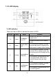
1.3 Front panel 1.3.
1.3.2 LED display 1) LED definition There are total 6 LEDs to indicate the status of UPS. LED No. 1~3 4 5 6 Colour Green Green Orange Red Name Function Load/Battery level LED Inverter status LED Bypass/Battery mode LED Fault/Warning mode LED 4 Indicate the load level in line mode or bypass mode. Indicate the battery level in battery mode. If it is turned on constantly, it shows that the load current is supplied from utility power or battery via the inverter.
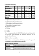
2) LED action summary LED No. 1 2 3 4 5 6 ! Bypass mode " Line mode Battery mode # # # " " Battery test mode # # # " ! Fault mode $ $ $ $ $ " Warning % % % $ % ! : Lightened according to load level #: Lightened according to battery level $: Depended on the fault/warning status %: Depended on the original display ": Lightened constantly !: Flashing 1.3.3 Button There is only one button for ON/OFF/Mute function on this product.
2) UPS response to the button Original mode Button action UPS response 6
1.
1.5 Product specification 1.5.1 Model description This manual is applicable to the following models: Model name 6K 6KS Power rating 6000VA/4200W 10K 10KS 10000VA/7000W Note: The model names without “S” represent standard model with internal battery. The model names with “S” represent long backup time model with external battery. 1.5.
1.5.4 Electrical Specification Model 6K 6KS Power 6000VA / 4200W 10K 10KS 10000VA / 7000W Input Current (Max.) 30A Voltage Range 32A 47A 50A 176~276VAC @ full load (110~276VAC @ half load) Frequency Range 46 ~ 54Hz @ 50Hz system / 56 ~ 64Hz @ 60Hz system Input Power Factor !0.98 @ full load Output Voltage 208*/220/230/240VAC (sine-wave) Synchronizing mains input @ line mode Frequency 50/60Hz ±0.
1.5.5 Standards * Safety IEC/EN 62040-1-1 * EMI Conducted Emission...............................:IEC/EN 62040-2 Category C3 Radiated Emission..................................:IEC/EN 62040-2 Category C3 *EMS ESD.........................................................:IEC/EN 61000-4-2 Level 4 RS........................................................ ...:IEC/EN 61000-4-3 Level 3 EFT......................................................... :IEC/EN 61000-4-4 Level 4 SURGE...........................
1) RS232 (optional) Pin assignment and description of DB-9 connector: Pin# Definition 2 TXD (output) 3 RXD (input) 5 GND 2) USB (optional) The USB port is compliance with USB 1.1 protocol for its communication software.
2. Installation 2.1 Installation Safety Instructions You must read the following safety instructions before installation! Installation Personnel This product must be installed only by qualified or professional personnel accord to safety instructions! Installation Environment Do not install and operate the UPS when water condensation happen which may occur if the UPS is moved directly from a cold to a warm environment. The UPS must be absolutely dry before being installed and operated.
Wiring & Grounding Installation and Wiring must be performed in accordance with the local electrical laws and regulations. The UPS must be securely grounded. Make sure earth connection and its reliability before connecting the power wires to the wiring terminal of the building. If there are external UPS battery cabinets, please make sure the battery cabinets have the equipotential earth bonding to the UPS main cabinet.
2.2.2 Inspect the appearance of the UPS to see if there is any damage during transportation. Do not turn on the unit and notify the dealer immediately if there is any damage or lack of some parts. 2.3 Installation steps of wiring 1) Make sure the mains wire & breakers in the building are enough for the rating of UPS to avoid the hazards of electric shock and fire. Note: Do not use the wall receptacle as the input power source for the UPS, as its rated current is less than the UPS’s maximum input current.
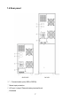
5) Remove the terminal block cover on the rear panel of UPS. Then connect the wires according to the following terminal block diagram: (Always connect the earth wire first!) Wiring connection on the 6K/10K rear panel Wiring connection on the 6KS/10KS rear panel Warning: (Only for standard model) Make sure the UPS is not turned on before installation. The UPS must not be turned on when doing wiring operation. Do not try to modify the standard model to the long back up time model.
Make sure a DC breaker or other protection device between UPS and external battery pack is installed. If not, please install it carefully. Switch off the battery breaker before installation. Pay highly attention to the rating battery voltage marked on the rear panel, the connection with wrong battery voltage may cause permanent damage of the UPS. Make sure the voltage of the battery pack is correct.
3. Operation 3.1 Operation Safety Instructions You must read the following safety instructions before operation! operation personnel Laymen can operate this product. operation warning Do not disconnect the earth conducting wire on the UPS or the building wiring terminals in any time since this would cancel the protective earth of the UPS system and all connected loads. The UPS output terminal may be electrically lived even if the UPS system is not connected to the mains power source.
3.2 Start the UPS with mains (AC source) 1) If the UPS is a long back up time model, with external battery banks, please switch on the battery breaker first; 2) If the wiring is correct, turn on the mains breaker. Then the power supply inside the UPS will be started automatically, the fans will run, and the panel will display with bypass mode. Note 1: If the UPS have been set to enable the bypass output, the output socket will have the voltage directly from mains after you turn on the input breaker.
lightened, and then black out one by one. After a few seconds of self-diagnoses, the UPS will be turned on to the battery mode and output the spec voltage. 3) After the UPS is turned on to battery mode normally, both the Inverter LED and Bypass/Battery LED will be on. The Load/Battery level LEDs will be lightened according to the battery capacity. The buzzer will beep according to the battery level. 3.4 Connect loads to UPS After the UPS is turned on, you can switch on the loads.
2) Suggest charging the batteries for 10 hours before use. Otherwise the backup time may be less than the standard value. 3.6 Discharge the batteries 1) When the UPS is in battery mode, the buzzer will beep according to different battery level. If the battery voltage drops to the alarming level, the buzzer will beep hurry (once every sec) to remind the user that the battery is low level and the UPS will be shutdown automatically soon.
3.8 Turn off the UPS with mains (AC source) 1) Firstly turn off the UPS (inverter) to bypass mode, please press the button continuously for more than 2 seconds. 2) After you press the button, the buzzer will beep once. All the LEDs will be lightened, and then black out one by one. Then the panel will display the bypass mode. Note 1: If the UPS have been set to enable the bypass output, the output socket will have voltage from mains directly after you turn off the UPS (inverter) to bypass mode.
3.10 Mute the buzzer 1) To mute the buzzer, please short-press the button. If you short-press it again after the buzzer muted, the beep will be returned. 2) It is not anytime the buzzer can be muted. If it is in warning/batterylow/overload, the buzzer can’t be muted unless the trouble is solved. 3) If it is in fault mode, short-press the button could transfer the continuous beep to once-every-second. 3.
3.13 Indication summary in normal operation Operating mode Line mode Battery level Load level LED 1 2 3 4 5 0~50% None 50~75% None 75~100% None % % % >100% Every 0.5 sec No output Bypass mode Every 2 min 0~50% % Every 2 min 50~75% % Every 2 min 75~100% % Every 2 min % Every 0.
4. Maintenance 4.1 Maintenance Safety Instructions You must read the following safety instructions before maintenance! Maintenance Personnel This product must be maintained only by qualified professional personnel accord to safety instructions! Risk of electric shock No matter the UPS is connected to the utility power or not, the output may have electricity. The parts (battery, capacitor) inside the unit may still have hazardous voltage after turning off the UPS.
Only use tools with insulated grips and handles when maintaining or repairing. Battery Only qualified personnel can replace the batteries! Do not short the positive and negative of the battery electrode. Batteries have a high short-circuit current and may cause a risk of serious shock or fire. When changing batteries, replace with the same quantity and the same type of batteries. Do not attempt to dispose of batteries by burning them. It could cause explosion.
4.2 Typical Trouble Shooting (1) Trouble shooting according to warning indication. LED 1-3 4 Possible cause 5 Action 6 % Fan abnormal, or % % % internal temperature is too high Check the fans. Check the loads. Check the ventilation, ambient temperature. % % % % I/P fuse open Check the I/P fuse and related power component. % Battery low abnormally or battery not connected (line % % & mode), or battery discharged over 14 hours Check the battery.
(2) Trouble shooting according to fault indication. LED 1 2 3 4 5 6 Possible cause Action Output short circuit Remove all the loads. Turn off the UPS. Check whether the output of UPS and loads is short circuit. Make sure the short circuit is removed, and the UPS has no internal faults before turning on again. Internal fault (inverter failed) Internal fault (inverter relay short) Overload Contact the distributor or service center. Contact the distributor or service center.
Note 1: when the UPS failed, the red Fault/Warning LED will be lightened constantly, and the buzzer will beep continuously. Note 2: When the UPS is fault, it will stop the power conversion of mains or battery, the original Load/Battery level LED will code the fault cause. Note 3: If the fault can’t be shoot, please contact the distributor or service center. (3) Trouble shooting in else cases.
2) The UPS should be charged once every 4 to 6 months if it has not been used for a long time. 3) In the regions of hot climates, the battery should be charged/ discharged every 2 months. The charging time should be >12 hours. 4) In normal conditions, the battery life lasts 3 to 5 years. If the battery is found in bad condition, earlier replacement should be made. 5) Do not replace the battery individually. All batteries should be replaced at the same time following the instructions of the supplier. 4.
5. Transport and Storage 5.1 Please transport the UPS only in the original packaging. 5.2 The UPS must be stored in the room where it is ventilated and dry.
614-00192-01 31