ViewPower User’s Manual Management Software for Uninterruptible Power Supply Systems
Table of Contents 1. ViewPower Overview .............................................................................................. 2 1.1. 1.2. 1.3. 1.4. 2. ViewPower Install and Uninstall ..................................................................... 3 2.1. 2.2. 2.3. 3. Introduction.............................................................................................................................. 2 Structure ..........................................................................
5.3.1. Real-time Control........................................................................................................ 39 5.3.2. Scheduled On/Off ....................................................................................................... 40 5.3.3. Scheduled Battery Self-Test ................................................................................. 41 5.4. View .......................................................................................................................
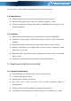
Google chrome, Safari, Opera, Avant Browser, and Deepnet Explorer. 1.3. Applications Monitor and manage the local UPS connected to local computer Monitor and manage other UPSs (with software installed) in LAN Remote monitor and manage other UPSs via INTERNET from remote PC (with software installed) 1.4.
Platforms supported by software are listed below: Windows 2000/XP/2003/Vista/2008/2012 (32-bit & x64-bit) Windows 7 / 8 (32-bit & x64-bit) Windows SBS 2011 Linux RedHat 8, 9 Linux RedHat Enterprise AS3, AS5, AS6 (32-bit) Linux RedHat Enterprise AS6 (64-bit) Linux RedHat Enterprise 5.2 (32-bit & 64-bit) Linux SUSE 10 (32-bit & 64-bit) Linux Cent OS 5.4 (32-bit & 64-bit) Linux Ubuntu 8.X, 9.X, 10.X (32-bit) Linux Ubuntu 10.X (64-bit) Linux Ubuntu 12.04 (32-bit & 64-bit) Linux Fedora 5 Linux OpenSUSE 11.
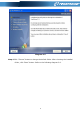
start the installation. Diagram 2-2 Step 1 After clicking install, it will display the installation in process. Refer to the diagram 2-3. Diagram 2-3 Step 2 Choose wanted language and click “OK” as diagram 2-4. Diagram 2-4 Step 3 Click “Next” to proceed to the next screen as Diagram 2-5.
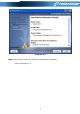
Diagram 2-5 Step 4 Click “Choose” button to change the default folder. After choosing the installed folder, click “Next” button. Refer to the following diagram 2-6.
Diagram 2-6 Step 5 Choose the shortcut folder and click “Next” button. Refer to the following diagram 2-7.
Diagram 2-7 Step 6 It will display the software summary before installation. Click “Install” button to start the installation and refer to Diagram 2-8.
Diagram 2-8 Step 7 Click “Done” button to confirm the installation completely. Refer to Diagram 2-9.
Diagram 2-9 Note: Please uninstall the previous version before install the new version software. If detecting installed ViewPower during installation, it will remind users to uninstall old version first. Refer to Diagram 2-10.
Diagram 2-10 2.3. Software Uninstall Note: Before uninstall software, you must stop all software programs first and then log in as “Administrator”! Otherwise it can't be uninstalled completely. Please choose Start >> All Programs >> ViewPower >> Uninstall. Then follow the on-screen instruction to uninstall the software. 3. Service Tray Application The Installer will leave a shortcut icon on your desktop. Simply click the shortcut.
Shortcut icon ViewPower icon 3.1. Start Monitor This software will be automatically activated when installing it as service application. At this time, users can remote monitor the ups through web browser even though users do not login in operation system. If service application can not be registered successfully, when starting up service tray service, it will automatically activate monitoring application. If it’s failed or stopped manually, simply click “Start Monitor” to activate it.
If port conflict occurs, you may modify value of tray port. The default setting for tray port is listed as below (Refer to section A in Diagram 3-1): Web Service port: 15178 Web service shutdown port: 8005 AJP port: 8009 You may modify the value of tray port to any number between 0 to 65536. If value entry is used, the system will remind users to enter another number again. NOTE1: Please do NOT modify port value unless port conflict occurs. This modification will affect remote monitoring website.
Save files to: The directory to save files. Online auto-update: If selected, it will automatically check if there is any new version launched online every 1 hour. If applying online upgrade, please follow below for configuration: 1. Select “Apply the proxy configuration”; 2. Enter IP address and port of server; 3. If ID identification is requested, select “Enable authentication” and enter User Name and Password. Connection test: Click this button to test if all configurations are set up well.
Diagram 3-1 3.3.4. Configuration Saved Click “Apply” button to save all changes in Configuration page. Click “Cancel” to stop the change. 3.4. Software Update Software update includes online update and manually update: Online Update: Click “Online Update” to search the latest software version. If there is new version, it will automatically download and update. Refer to Diagram 3-2: Diagram 3-2 Manually Update: Users can manually update the software.
Diagram 3-3 2.Click “Browse” to choose file directory. And then click “Upgrade” to upgrade software. Refer to Diagram 3-4. Diagram 3-4 3.5. Debug Mode If debug mode is activated, the software will record process of UPS searching and communication into log so that it can be analyzed when communication failure occurs. Start: Click “Start” to activate debug mode. Refer to Diagram 3-5. Click “Stop” to stop recording. Refer to Diagram 3-6.
Diagram 3-6 Logs: Click “Logs” to check the log records. Refer to Diagram 3-7. Diagram 3-7 3.6. Open Monitor Click “Open Monitor” to open monitor page. 3.7. Message Board Users can check message board for event list.
Diagram 3-8 3.8. Exit Click “Exit” to exist service application 4.
Diagram 4-1 A. Function Menu offers complete tool-set for navigating and setting the GUI. B. Shortcut Menu provides short cuts to more commonly used functions. C. Current Monitoring Information displays user ID and monitored UPS name. D. UPS Navigation indicates all UPS locations in networked environment. E. Main Window contains information and/or controls that change with each function menu or shortcut menu selected. 4.1. Refresh Click the Refresh icon to refresh screen (Refer to Diagram 4-2).
Diagram 4-2 4.2. UPS Searching Step 1 Click the UPS Searching icon Step 2 Click the UPS search icon to search UPS devices in LAN or INTERNET. (Refer to Diagram 4-3).
Manual Internet search: 1. Precise search: Input the designated IP address, and then click the search button for searching 2. Related search: Input a IP address ranging, and click the search button to activate the searching Note: The period last on related search is proportional to the range of provided IP address 4.3. UPS Navigation It displays all UPSs found through UPS searching function.
Diagram 4-4 NOTE: This display screen may be different for different types of UPS. 4.3.2. UPS Remote Control & Monitor If you want to control and set up the remote UPS, you must log in as an administrator. There are two ways to remote monitor UPS: Method one: Double click any UPS from LAN or INTERNET and it will pop up a message window to confirm the monitoring action. Refer to below diagram 4-5.
Diagram 4-5 Select “Yes” and it will open another new window to display remote UPS information. Refer to Diagram 4-6. Diagram 4-6 NOTE: This display screen may be different for different types of UPS. Method 2: Open browser and enter the remote PC IP address and 15178. For example, remote PC IP address is 202.16.53.142. Please enter http://202.16.53.142:15178/ViewPower in browser. Refer to Diagram 4-7 Diagram 4-7 5. ViewPower Function Menu 5.1. ViewPower Configuration 5.1.1.
software, please login first and modify the password. The default password is “administrator” at first log in. Users can only browse UPS status and information as Guest status without login as an Administrator. Guest can NOT control or executive any setting. Modify password Step 1 Select ViewPower Configuration>>Password. Refer to Diagram 5-1. Diagram 5-1 Step 2 Enter old password, new password, and retype new password in confirm password column to modify password for administrator.
Diagram 5-2 Step 2 Select communication port and baud rate. Step 3 Enter mobile phone numbers in “Phone no.” column and click “Add” button to add phone no. in Receivers List. To delete numbers, simply select phone no. from “Receivers list” and click “Delete”. Step 4 Click “Apply” button to save all changes. The “Test” button can be used to send test SMS to confirm the correct operation. If all parameters are set up correctly, system will send a test message to all receivers and pop up a successful message.
Diagram 5-3 Diagram 5-4 NOTE: It’s required to plug-in GSM Modem if sending SMS to mobile phone. 5.1.3. E-mail Configuration This feature enables the configuration to send alarm mail by SMTP server. For the event receiving list, please configure in “Event Action” column (refer to section 5.1.4). To use this function, the e-mail service must be correct configured on the computer. All values in this function page are default empty.
SMTP information, e-mail account, and password. Besides, the sender account should be allowed for SMTP/POP3 forwarding. Step 1 Select ViewPower Configuration >> E-mail. Refer to Diagram 5-5. Diagram 5-5 Step 2 Enter SMTP server, SMTP port, Send from E-mail address, User name and password. Click checkbox of password authentication needed for password verify.
5.1.4. Event Action Configuration It’s to configure response actions for UPS events. Software provides six response actions after events occur. 1. Event record: It will record event to data log in software after events occur. This function is default selected. 2. Computer alarm: Computer will beep to remind users after events occur. This function is only available for Windows OS. 3. Warning dialog (local): It will pop up a message dialog around the software orange plug icon in taskbar after events occur.
Step 2 Select a specific event from “Event List” and then action method page will be active on the right-hand column. Step 3 Select desired action methods by clicking checkbox. Step 4 Click “Apply” button to save all configurations. NOTE1: When editing receiver list in SMS or e-mail columns, it’s necessary to refresh the event action page to reload the updated receiver list. NOTE2: It is requested to have following conditions for successful broadcast. 1. All receiving PCs must have installed software. 2.
Diagram 5-7 Step 2 Add: Enter MAC address and click “Add” button to add in MAC List. Delete: Select one from list and click “Delete” button. Test: Select one from list and click “Test” button. Then it will execute Wake-on-LAN test. NOTE: The MAC address format example: 01-1F-C6-C7-E0-08. 5.1.6. Com.Port Plug And Play Setting To real-time monitor UPS device, the software will scan each com. port anytime. In this way, it will occupy com. port. This function will release some com.
5.1.7. Log Setting Users can set up “Record Interval”, “The max. Numbers of logs for historical data”, and “The max. Numbers of logs for historical events” according to real situation. The setting range for “Record internal” is 30~600 seconds. It will effect history data displayed under View –> History. The setting range for “The max. Numbers of logs for historical data” is 100000~100000000. It will effect displayed data under View –> History. The setting rang for “The max.
Diagram 5-10 Step 2 Password setting/change menu for ModBus. Real-time control will be available when the ModBus password is the same to the UPS password. Step 3 Com. port setting: The default ID for nominated com. port is 1; Selectable baud rates are 1200, 2400, 4800, 9600, and 19200. The default setting is 4800; Selectable data bit is 7 and 8. The default setting is 8; Selectable stop bit is 1 and 2. The default setting is 1; Supported parity is ODD parity, even parity and NONE.
remote shut down PCs which are powered by monitored UPS. Step 1 Select UPS Setting >> Local Shutdown or click shortcut icon . Refer to Diagram 5-11. Diagram 5-11 NOTE: This screen may be different for different types of UPSs. Step 2 Select shutdown conditions and power-off options, set delay time to shutdown system. Step 3 Enter time for pop-up dialog before shutdown and warning interval in Warning Dialog Setting area. Step 4 Click “Apply” button to save all data.
Local shutdown when the capacity of battery down to xx %: When clicking this checkbox, local UPS will still operate in battery mode until the battery capacity is down to xx%. Until then, local PC will shut down. The setting range is 0%-100%. Also shut down UPS after shutting down the local system: When clicking this checkbox, monitored UPS will shut down after local system shuts down. The UPS shutdown time will be later than system complete shutdown time. The default setting is clicked.
Delay time to shutdown system: Enter the delay time to shut down the operating system. The value range is from 1 to 99 minutes. On shutdown execute file: Enter the path of execute file. Warning Dialog Setting: Pop-up dialog before shutdown: Timer setting for pop-up warning dialog displayed in local PC. Local PC will pop up a warning dialog before system starts to shut down. The range is from 1 to 999 seconds. Warning dialog interval: Reminding dialog interval setting.
Step 3 Add/Delete remote system IP address. Step 4 Click “Apply” button to save all data. NOTE: Click “Default” button to recover the default setting. Conditions: When the UPS is running from battery, shut down the remote systems after xx min xx sec: When clicking the checkbox, remote systems which are powered by monitored UPS will shut down after monitored UPS running on battery mode for xx min xx sec. The maximum setting number for minutes is 999, and for seconds is 59.
Diagram 5-13 NOTE: This screen may be different for different types of UPSs. Step 2 Select the functions by clicking “Enable” or “Disable” button. Or change the numbers by clicking up-down arrows or modify the numbers directly in the number column. Step 3 Click “Apply” button to save the settings. Each function setting is saved by clicking each “Apply” button. NOTE1: Any functions which are not supported by UPS will not be able to access. NOTE2: Click “Default” button to recover the default setting.
devices when UPS is off. Vice versa. Converter mode: If enabled, the UPS will operate in converter mode. Vice versa. ECO mode: If enabled, the UPS will operate in ECO mode when input voltage is within acceptable range. Vice versa. Battery open status check: If enabled, the monitored UPS will check if the battery connection ok or not when UPS is turned on. Cold start: If disabled, the UPS can be turned on only when AC is normally connected to UPS. Vice versa.
Voltage range for ECO mode: Set acceptable voltage range for ECO mode. 5.2.4. Purchasing Information Users can enter UPS purchasing date, battery purchasing date, UPS warranty time, battery warranty time, battery lifecycle, battery replacement reminder. Step 1 Select UPS Setting >> Purchasing Information. Refer to Diagram 5-14. Diagram 5-14 Step 2 Please fill out purchasing information. Step 3 Click “Apply” button to save all data. 5.3. Control 5.3.1.
Diagram 5-15 NOTE: This screen may be different for different types of UPSs. Step 2 Choose real-time control function by clicking “Start” button on each function section. You can real-time control the UPS by executing following operation: Alarm control: Click “On” to turn on the UPS alarm and “Off” to turn off the UPS alarm immediately. UPS turn On/Off: Click “On” to turn on the UPS and “Off” to turn off the UPS immediately.
action in the same time. If multiple actions have been specified at the same time, some of these actions may be ignored. Any actions which are not supported by the UPS will be ignored. Step 1 Select “Control” >> Scheduled On/Off. Refer to Diagram 5-16. Diagram 5-16 Step 2 Set frequency and setting time on the right column. NOTE: Rules for setting time. Daily schedule – Power-off time should be earlier than power-on time. It only applies to set power-on time and power-off time within the same day.
is recommended to set only one action in the same time. If multiple actions have been specified at the same time, some of these actions may be ignored. Any actions which are not supported by the UPS will be ignored. Step 1 Select Control >> Battery Self-Test. Refer to Diagram 5-17. Diagram 5-17 Step 2 Select method and time parameters. There are three self-test methods: 10-second self-test: Battery will discharge for 10 seconds. Self-test: Users can set battery discharge time for self-test.
5.4.1.1. Power Flow In the Power Flow window, it’s shown the internal dynamic working scheme of the UPS. Green/black flow means OK and working. Grey bar means that the object is present but not in use at the moment. There are four information blocks to display details for input, output, UPS and battery information. Input information includes input voltage and input frequency. Output information includes output voltage, output frequency, load level, and output current.
Diagram 5-19 NOTE: This screen may be different for different types of UPSs. In the UPS Info window, it’s shown detailed UPS real-time information. 5.4.1.3. Diagram In the Diagram window, it’s shown real-time monitored UPS data including voltage, frequency, load, battery, temperature information in diagram. Step 1 Select View >> Status >> Diagram. Refer to Diagram 5-20.
Diagram 5-20 NOTE: This screen may be different for different types of UPSs. Step 2 Select monitoring parameters on left-hand tab to switch diagram. Input voltage monitoring shows any change for input voltage. Output voltage monitoring shows any change for output voltage. Input frequency monitoring shows any change for input frequency Output frequency monitoring shows any change for output frequency.
data and improve the current electricity environment according to history data. Step 1 Select View >> History >> Event Log. Refer to Diagram 5-21. Diagram 5-21 Step 2 Select UPS from com. port list. Users still can retrieve old data saved in the software even though the UPS is no longer connected to local system. Step 3 Select time period by clicking calendar icon. Then click “Browse” button to get list of all history events during selected period time.
event, load event, input event, parallel system event and communication event. Step 1 Select View >> History >> Event Statistics. Or click shortcut icon . Refer to Diagram 5-22. Diagram 5-22 Step 2 Select UPS from com. port list. Users still can retrieve old data saved in the software even though the UPS is no longer connected to local system. Step 3 Select two periods from clicking “calendar” icon. Then click “Browse” button. The result statistics will be listed in below table according to event types.
Diagram 5-23 Step 4 Click “Print” button to print event statistics. 5.4.2.3. Data In the window of Data, it shows UPS power data in figures during selected period time. Software also offers print, save as, and delete functions. Step 1 Select View >> History >> Data. Refer to Diagram 5-24.
Diagram 5-24 NOTE: This screen may be different for different types of UPSs. Step 2 Select UPS from com. port list. Users still can retrieve old data saved in the software even though the UPS is no longer connected to local system. Step 3 Select the starting time and ending time by clicking calendar icon. Then click “Browse” button to get the data table. “Print”: Print the listed data table. “Delete”: Select specific data and click “Delete” button to delete the record.
Step 2 Select UPS from com. port list. Users still can retrieve old data saved in the software even though the UPS is no longer connected to local system. Step 3 Select cycle and period time. Then click “Browse” button to get the diagram. Step 4 Select monitoring parameters on left-hand tab to switch diagram. 5.5. Format Temperature Unit: There are two temperature units for selecting: Centigrade and Fahrenheit. Default setting is centigrade.
About: Click “Help” menu and select “About” item. It represents the copyright information about software Help: Click “Help” menu and select “Online help” item. It will open the help manual. Before operating software, please read manual carefully.
Appendix A: Glossary Local PC (system): The local PC (system) is physically connected to UPS with communication port. Remote PCs (systems): The remote PCs (systems) are physically powered by UPS without communication port connection.