ViewPowerMini User’s Manual Management Software for Uninterruptible Power Supply Systems
Table of Contents 1. ViewPowerMini Overview..................................................................................2 1.1. 1.2. 1.3. 2. ViewPowerMini Install and Uninstall ..........................................................3 2.1. 2.2. 2.3. 3. Introduction..............................................................................................................................2 Structure...................................................................................................
5.3.3. Scheduled Battery SelfTest.................................................................................51 5.4. View.............................................................................................................................................52 5.4.1. Status.................................................................................................................................52 5.4.2. History..................................................................................
dialog for current UPS status. NOTE: Tray icon only exists under Windows OS. 1.3. Features l Realtime dynamic graphs of UPS data (voltage, frequency, load level, battery capacity) l Safely OS shutdown and protection from data loss during power failure l Warning notifications via audible alarm, popup screen, broadcast, mobile messenger, and email l Scheduled UPS on/off, battery test, programmable outlet control, and audible alarm control l Password security protection 2.
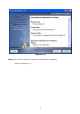
Ø Linux Cent OS 5.4 (32bit) Ø Linux Ubuntu 8.X, 9.X, 10.X (32bit) Ø Linux Fedora 5 Ø Linux OpenSUSE 11.2 (32bit & 64bit) Ø Linux Debian 5.x, 6.x (32bit) Ø Linux Debian 6.x (64bit) Ø Mac OS 10.6 / 10.7 / 10.8 (x64bit) 2.2. Software Install Step 1 After clicking install, it will display the installation in process. Refer to the diagram 23. Diagram 23 Step 2 Choose wanted language and click “OK” as diagram 24.
Diagram 24 Step 3 Click “Next” to proceed to the next screen as Diagram 25. Diagram 25 Step 4 Click “Choose” button to change the default folder. After choosing the installed folder, click “Next” button. Refer to the following diagram 26.
Diagram 26 Step 5 Choose the shortcut folder and click “Next” button. Refer to the following diagram 27.
Diagram 27 Step 6 It will display the software summary before installation. Click “Install” button to start the installation and refer to Diagram 28.
Diagram 28 Step 7 Click “Done” button to confirm the installation completely. Refer to Diagram 29.
Diagram 29 Note: Please uninstall the previous version before install the new version software. If detecting installed ViewPowerMini during installation, it will remind users to 2.3. Software Uninstall Note: Before uninstall software, you must stop all software programs first and then log in as “Administrator”! Otherwise it can't be uninstalled completely. Please choose Start >> All Programs >> ViewPowerMini >> Uninstall. Then follow the onscreen instruction to uninstall the software. 3.
mouse. Refer to below diagram. Or, use the Start Menu method; Start >> All Programs >> ViewPowerMini >> ViewPowerMini Shortcut icon ViewPowerMini icon 3.2. Icon and Software status l Monitoring application is not activated successfully: l Monitoring application is activated as service mode: l Monitoring application is activated as application mode: 3.3. Configuration 3.3.1. SNMP Manager SNMP Manager is a plugin utility for ViewPowerMini to search and operate all SNMP devices in the LAN.
Diagram 31 A. Function menu offers toolset for setting SNMP devices. B. SNMP device list can list down all SNMP devices with IP address. C. Configuration area includes Basic info, IP settings, online upgrade, system management, and static trap address. D. Output window displays all messages for operations 3.3.1.1. SNMP Device List The default value in window list would be current PC IP address. For example, if IP address of current PC is “192.168.102.10”, it will display “192.168.
Diagram 32 Delete You may select IP address from the list and remove it by clicking “Del” button. SNMP Status It will display SNNP status, 0 or 1, after selecting IP from the IP list. If there is program inside of selected SNMP card, the status becomes 1. If not, it will display 0. If no IP address is selected, it will display ““ as default. Refer to Diagram 33.
Diagram 33 Reset If it is required to restart the IP addresses of devices, please select the checkbox of "SNMP reset enable" and click "Reset" button. Then, if login is confirmed, you can restart the device. Steps are as follows: Step1: Select IP address needed to restart IP from the list. Then, "SNMP reset enable" will become available to select. Refer to Diagram 34.
Step2: Click checkbox of "SNMP reset enable". Then, "Reset" button will become available to click. Refer to Diagram 35. Diagram 35 Step3: Click "Reset" button and it will pop up a message to confirm this operation. Refer to Diagram 36. Diagram 36 Step4: If "Yes" is selected, it’s requested to log in first. If "No" is selected, it will stop this operation. Refer to Diagram 37.
Diagram 37 Step5: Enter the correct password and click "Login" button. The target device will be restarted. NOTE: If changing the MAC address of current device before reboot and the current device is applying DHCP (Automatically obtain IP address) method, you need to manually click "Scan" button to scan. Use system time If “Use system time” is selected, the SNMP card will apply PC system time. Refer to Diagram 38.
Diagram 38 3.3.1.2. Function Menu 3.3.1.2.1. System 3.3.1.2.1.1. Login It’s necessary to verify ID to remote access SNMP devices. The default password is “12345678”. Step 1: Select System >> Login Step 2: Enter default password and then click “Login” button. Or click “Cancel” to cancel login. Refer to Diagram 39.
Diagram 39 Logout Clear all currently saved passwords. Quit Select “Quick” to exit SNMP Manager. 3.3.1.2.2. Settings Basic Info User can manually enter basic information of SNMP cards such as UPS name, Address, and Note for verification. Refer to Diagram 310.
Diagram 310 IP Setting Diagram 311 Part A: There are two methods to obtain IP address. Select IP address from IP list. It will display MAC address of device in the output window. Refer to section A in Diagram 311. l Automatically obtain IP address (DHCP) It will allow system to automatically obtain IP addresses.
service provided in LAN, the default IP will display as “192.168.102.230”, Net mask as “255.255.255.0” and default gateway as “0.0.0.0”. Simply click “Apply” button to apply this change. l Use a static IP address It will allow users to enter static IP address for SNMP devices. When entering IP address, Subnet mask, and gateway address, simply click “Apply” button to apply this change. Part B: Enter the DNS and click “Apply” button. Refer to section B in Diagram 312.
IP address of current PC in LAN. If applying upgrade for Modbus Web Server in specific networking, FTP server IP address will be IP address of current PC in Internet. Step2: Click “Browse” button to choose program file. Refer to Diagram 313. Diagram 313 Step3: Click “Upgrade” button to execute upgrade action. Refer to Diagram 314. Diagram 314 Step4: When upgrade is complete, you may check the message in output window. Refer to Diagram 315.
Diagram 315 NOTE: If abnormal situation occurs during upgrade process, the system will automatically restart the upgrade operation. If this interruption occurs five times, then, system will automatically stop this operation. At this time, please check if LAN is working well. System management Diagram 316 Part A: You can set SNMP protocol version for selected or all devices.
SNMP protocol version first. The default setting is V2. If choosing V3, it’s also necessary to set encrypt. Select devices to apply this setting. l Select device: Set SNMP protocol version for selected SNMP devices from device list. l Select all: Set SNMP protocol version for all SNMP devices from device list. Then, click “Apply” button to complete version setting. Part B: You may modify single password for one SNMP device or all passwords for all SNMP devices.
NOTE: This software allows SNMP device to send trap messages to 2 static trap addresses and 8 dynamic trap addresses. It will default define host computer with software installed as a dynamic trap address. If communication failure occurs between SNMP card and host computer for over 10 minutes, it will stop sending trap message. 3.3.2.
Diagram 318 3.3.3. Configuration Saved Click “Apply” button to save all changes in Configuration page. Click “Cancel” to stop the change. 3.4. Software Update Software update includes online update and manually update: l Online Update: Click “Online Update” to search the latest software version.
version, it will automatically download and update. Refer to Diagram 319: Diagram 319 l Manually Update: Users can manually update the software. Follow below steps: 1.Click “Manually Update” from function menu. Refer to Diagram 320. Diagram 320 2.Click “Browse” to choose file directory. And then click “Upgrade” to upgrade software. Refer to Diagram 321. Diagram 321 3.5. Open Monitor Click “Open Monitor” to open monitor page. 3.6. Message Board Users can check message board for event list.
Diagram 322 3.7. Exit Click “Exit” to exist service application 4.
Diagram 41 A. Function Menu offers complete toolset for navigating and setting the GUI. B. Shortcut Menu provides short cuts to more commonly used functions. C. Current Monitoring Information displays user ID and monitored UPS name. D. UPS Navigation indicates all UPS locations in networked environment. E. Main Window contains information and/or controls that change with each function menu or shortcut menu selected. 4.1. UPS Navigation It displays all UPSs found through UPS searching function.
l Purchasing information means UPS purchasing date, battery purchasing date, warranty for UPS, and warranty for battery. Diagram 42 NOTE: This display screen may be different for different types of UPS. 4.1.2. UPS Remote Control & Monitor If you want to control and set up the remote UPS, you must log in as an administrator. There are two ways to remote monitor UPS: Ø Method one: Double click any UPS from LAN or INTERNET and it will pop up a message window to confirm the monitoring action.
Diagram 43 Select “Yes” and it will open another new window to display remote UPS information. Refer to Diagram 44. Diagram 44 NOTE: This display screen may be different for different types of UPS.
5. ViewPowerMini Function Menu 5.1. ViewPowerMini Configuration 5.1.1. Password Configuration It’s password configuration for administrator only. Before operating and configuring the software, please login first and modify the password. The default password is “administrator” at first log in. Users can only browse UPS status and information as Guest status without login as an Administrator. Guest can NOT control or executive any setting.
be at least 6 digits) Then click “Apply” button to successfully modify password for administrator. NOTE1: Simply click “Login” button on the top right corner to log in the software. NOTE2: If password is forgotten, it’s necessary to reinstall the software. 5.1.2. SMS Configuration It’s for entering SMS receiver list. In the event of an alarm condition occurring, a message about UPS status will be sent to the specified users via mobile phone.
test SMS to confirm the correct operation. If all parameters are set up correctly, system will send a test message to all receivers and pop up a successful message. (Refer to Diagram 53) Otherwise, it will pop up a failure dialog to indicate there is an error for parameter setting.
Diagram 54 NOTE: It’s required to plugin GSM Modem if sending SMS to mobile phone. 5.1.3. Email Configuration This feature enables the configuration to send alarm mail by SMTP server. For the event receiving list, please configure in “Event Action” column (refer to section 5.1.4). To use this function, the email service must be correct configured on the computer. All values in this function page are default empty. This action can’t be executed without the SMTP information, email account, and password.
server”, then click “Apply” button. Step 3 Enter correct email accounts in Email column. Then click “Add” to add into receivers list. To delete email account, simply select accounts from Receivers list and click “Delete” button. Step 4 Click “Apply” to save all changes. The “Test” button can be used to send a test email to all receivers to confirm correct operation. When the test emails are successfully sent to specific recipients, it will pop up a successful message on operated PC.
Diagram 56 NOTE: The displayed event list may be different for different types of UPSs. Step 2 Select a specific event from “Event List” and then action method page will be active on the righthand column. Step 3 Select desired action methods by clicking checkbox. Step 4 Click “Apply” button to save all configurations. NOTE1: When editing receiver list in SMS or email columns, it’s necessary to refresh the event action page to reload the updated receiver list.
Step 1 Select ViewPowerMini Configuration >> Wake on LAN. Refer to Diagram 57. Diagram 57 Step 2 Add: Enter MAC address and click “Add” button to add in MAC List. Delete: Select one from list and click “Delete” button. Test: Select one from list and click “Test” button. Then it will execute WakeonLAN test. NOTE: The MAC address format example: 011FC6C7E008. 5.1.6. Com.Port Plug And Play Setting To realtime monitor UPS device, the software will scan each com. port anytime.
Diagram 58 Step 2: Click “Refresh” to reload the status of com. ports. Step 3: Click “Forbid scanned” to stop scanning on this com. port. Click “Allow scanned” to start scanning on this com. port. 5.1.7. Log Setting Users can set up “Record Interval”, “The max. Numbers of logs for historical data”, and “The max. Numbers of logs for historical events” according to real situation. The setting range for “Record internal” is 30~600 seconds. It will effect history data displayed under View –> History.
Diagram 59 Step 2 Enter data in the screen. Step 3 Click “Apply” button to save all data. Step 4 Click “Default” button to recover the default setting. 5.1.8. ModBus Communication Setting It will display all connected PCs through ModBus. Step 1 Select ViewPowerMini configuration>> ModBus Communication Setting Refer to Diagram 510.
Diagram 510 Step 2 Password setting/change menu for ModBus. Realtime control will be available when the ModBus password is the same to the UPS password. Step 3 Com. port setting: Selectable baud rates are 1200, 2400, 4800, 9600, and 19200. The default setting is 19200; Selectable data bit is 7 and 8. The default setting is 8; Selectable stop bit is 1 and 2. The default setting is 1; Supported parity is ODD parity, even parity and NONE. The default setting is NONE.
Diagram 511 Ø Text Message: The description of the dry contact event. Ø Default dry Contact: Define dry contact no. to send event message. There are five selections: none, 1, 2, 3 and 4. If selecting any value from 1 to 4, any environmental monitoring device (EMD) which is detected defined event will send event message. If selecting none, it means this event is defined as special event. Then, users can assign specific environmental monitoring device (EMD) to receive this event message.
Diagram 512 l Alarm Settings: Set up alarm range for temperature and humidity. If detected figures are out of setting range, it will send alarm message. Refer to Diagram 513.
5.2. UPS Setting 5.2.1. Local Shutdown It’s shutdown setting for local PC which is directly connected to monitored UPS with communication port. This configuration enables system shutdown of local PC or to remote shut down PCs which are powered by monitored UPS. Step 1 Select UPS Setting >> Local Shutdown or click shortcut icon . Refer to Diagram 514. Diagram 514 NOTE: This screen may be different for different types of UPSs.
Step 4 Click “Apply” button to save all data. NOTE: Click “Default” button to recover the default setting. Conditions: l When the UPS is running from battery, shut down local system after xx min xx sec: When clicking the checkbox, local PC will start to shut down after monitored UPS works on battery mode for xx min xx sec time. The maximum setting number for minutes is 999, and for seconds is 59.
power off. The default setting is clicked. Poweroff option: Selecting poweroff method for above shutdown system. l Shutdown: When clicking the checkbox, the selected system will shut down. The default setting is clicked. l Sleep mode: When clicking the checkbox, selected system will suspend the system instead of a normal shutdown. But this function is only supported by Windows 2000 or higher on supported hardware. Delay time to shutdown system: Enter the delay time to shut down the operating system.
Diagram 515 Step 2 Select remote shutdown conditions. Step 3 Add/Delete remote system IP address. Step 4 Click “Apply” button to save all data. NOTE: Click “Default” button to recover the default setting. Conditions: l When the UPS is running from battery, shut down the remote systems after xx min xx sec: When clicking the checkbox, remote systems which are powered by monitored UPS will shut down after monitored UPS running on battery mode for xx min xx sec.
5.2.3. Parameter Setting Some UPS functions can be set and changed via software. Parameter setting includes backup time setting for P1, battery number setting, voltage and frequency range setting for bypass mode, and voltage range setting for ECO mode. Step 1 Select UPS Setting >> Parameter Setting. Refer to Diagram 516. Diagram 516 NOTE: This screen may be different for different types of UPSs. Step 2 Select the functions by clicking “Enable” or “Disable” button.
l Alarm at battery mode: If disabled, UPS will not alarm when it’s working at battery mode. Vice versa. l Auto reboot: If enabled, UPS will auto recover when AC is recovering. Vice versa. l Bypass when UPS is off: If enabled, AC will directly provide power to connected devices when UPS is off. Vice versa. l Converter mode: If enabled, the UPS will operate in converter mode. Vice versa. l ECO mode: If enabled, the UPS will operate in ECO mode when input voltage is within acceptable range.
frequency range in bypass mode. Ø Maximum and minimum voltage: When UPS is on bypass mode and input voltage is out of setting range, UPS will enter battery mode. Ø Maximum and minimum frequency: When UPS is on bypass mode and input frequency is out of setting range, UPS will enter battery mode. l Voltage range for ECO mode: Set acceptable voltage range for ECO mode. 5.2.4.
5.3.1. Realtime Control Step 1 Select Control >> Realtime Control or click shortcut icon . Refer to Diagram 518. Diagram 518 NOTE: This screen may be different for different types of UPSs. Step 2 Choose realtime control function by clicking “Start” button on each function section. You can realtime control the UPS by executing following operation: l UPS turn On/Off: Click “On” to turn on the UPS and “Off” to turn off the UPS immediately.
5.3.2. Scheduled On/Off Scheduled UPS on/off can be executed once, daily, weekly. In the window “Scheduled On/Off Setting”, users can choose time parameters. It is recommended to set only one action in the same time. If multiple actions have been specified at the same time, some of these actions may be ignored. Any actions which are not supported by the UPS will be ignored. Step 1 Select “Control” >> Scheduled On/Off. Refer to Diagram 519.
5.3.3. Scheduled Battery SelfTest Scheduled battery selftest can be executed once, daily, weekly, or monthly. In the window of “Scheduled Battery SelfTest Setting”, users can choose time parameters. It is recommended to set only one action in the same time. If multiple actions have been specified at the same time, some of these actions may be ignored. Any actions which are not supported by the UPS will be ignored. Step 1 Select Control >> Battery SelfTest. Refer to Diagram 520.
5.4. View 5.4.1. Status 5.4.1.1. Power Flow In the Power Flow window, it’s shown the internal dynamic working scheme of the UPS. Green/black flow means OK and working. Grey bar means that the object is present but not in use at the moment. There are four information blocks to display details for input, output, UPS and battery information. l Input information includes input voltage and input frequency. l Output information includes output voltage, output frequency, load level, and output current.
Select View >> Status >> UPS Info. Refer to Diagram 522. Diagram 522 NOTE: This screen may be different for different types of UPSs. In the UPS Info window, it’s shown detailed UPS realtime information. 5.4.1.3. Diagram In the Diagram window, it’s shown realtime monitored UPS data including voltage, frequency, load, battery, temperature information in diagram. Step 1 Select View >> Status >> Diagram. Refer to Diagram 523.
Diagram 523 NOTE: This screen may be different for different types of UPSs. Step 2 Select monitoring parameters on lefthand tab to switch diagram. l Input voltage monitoring shows any change for input voltage. l Output voltage monitoring shows any change for output voltage. l Input frequency monitoring shows any change for input frequency l Output frequency monitoring shows any change for output frequency.
Diagram 524 Note: This information is only available when SNMP card is connected with Environmental monitoring device (EMD). 5.4.2. History 5.4.2.1. Event Log In the Event Log window, it’s shown all history events. Users can analyze the history data and improve the current electricity environment according to history data. Step 1 Select View >> History >> Event Log. Refer to Diagram 525.
Diagram 525 Step 2 Select UPS from com. port list. Users still can retrieve old data saved in the software even though the UPS is no longer connected to local system. Step 3 Select time period by clicking calendar icon. Then click “Browse” button to get list of all history events during selected period time. Step 4 Print/Delete/Export function keys Ø “Delete/Delete All”: To delete specific event, simply select that event and then click “Delete” button.
Diagram 526. Diagram 526 Step 2 Select UPS from com. port list. Users still can retrieve old data saved in the software even though the UPS is no longer connected to local system. Step 3 Select two periods from clicking “calendar” icon. Then click “Browse” button. The result statistics will be listed in below table according to event types. Refer to Diagram 527.
Diagram 527 Step 4 Click “Print” button to print event statistics. 5.4.2.3. Data In the window of Data, it shows UPS power data in figures during selected period time. Software also offers print, save as, and delete functions. Step 1 Select View >> History >> Data. Refer to Diagram 528.
Diagram 528 NOTE: This screen may be different for different types of UPSs. Step 2 Select UPS from com. port list. Users still can retrieve old data saved in the software even though the UPS is no longer connected to local system. Step 3 Select the starting time and ending time by clicking calendar icon. Then click “Browse” button to get the data table. Ø “Delete”: Select specific data and click “Delete” button to delete the record.
Diagram 529 NOTE: This screen may be different for different types of UPSs. Step 2 Select UPS from com. port list. Users still can retrieve old data saved in the software even though the UPS is no longer connected to local system. Step 3 Select cycle and period time. Then click “Browse” button to get the diagram. Step 4 Select monitoring parameters on lefthand tab to switch diagram. 5.4.2.5.
Diagram 530 Step 2 Select UPS and select the starting time and ending time by clicking calendar icon. Then click “Browse” button to get the data table. Delete/Delete all Ø “Delete”: Select specific data and click “Delete” button to delete the record. Ø “Delete all”: Click “Delete all” button to delete all records on the listed table. Ø “Export”: Click “Export” button to save listed table to local PC in .PDF file. 5.5.
√ Chinese(Traditional) √ English √ German √ Italian √ Polish √ Portuguese √ Russian √ Spanish √ Ukrainian √ French √ Turkish √ Czech 5.7. Help 6. About: Click “Help” menu and select “About” item. It represents the copyright information about software 7. Help: Click “Help” menu and select “Online help” item. It will open the help manual. Before operating software, please read manual carefully.
Appendix A: Glossary l Local PC (system): The local PC (system) is physically connected to UPS with communication port. l Remote PCs (systems): The remote PCs (systems) are physically powered by UPS without communication port connection.