Powerware® 9125 Two-in-One UPS 2500/3000 VA User’s Guide
Class A EMC Statements FCC Part 15 NOTE This equipment has been tested and found to comply with the limits for a Class A digital device, pursuant to part 15 of the FCC Rules. These limits are designed to provide reasonable protection against harmful interference when the equipment is operated in a commercial environment.
Requesting a Declaration of Conformity Units that are labeled with a CE mark comply with the following harmonized standards and EU directives: S Harmonized Standards: EN 50091-1-1 and EN 50091-2; IEC 60950 Third Edition S EU Directives: 73/23/EEC, Council Directive on equipment designed for use within certain voltage limits 93/68/EEC, Amending Directive 73/23/EEC 89/336/EEC, Council Directive relating to electromagnetic compatibility 92/31/EEC, Amending Directive 89/336/EEC relating to EMC The EC Decla
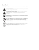
Special Symbols The following are examples of symbols used on the UPS or accessories to alert you to important information: RISK OF ELECTRIC SHOCK - Indicates that a risk of electric shock is present and the associated warning should be observed. CAUTION: REFER TO OPERATOR’S MANUAL - Refer to your operator’s manual for additional information, such as important operating and maintenance instructions. RJ-45 RECEPTACLE - For 230V models only: this receptacle provides network interface connections.
Table of Contents 1 Introduction . . . . . . . . . . . . . . . . . . . . . . . . . . . . . . . . . . . . . . . . . . . . . . . . . . . . . . . . . 1 2 Safety Warnings . . . . . . . . . . . . . . . . . . . . . . . . . . . . . . . . . . . . . . . . . . . . . . . . . . . . . 3 3 Installation . . . . . . . . . . . . . . . . . . . . . . . . . . . . . . . . . . . . . . . . . . . . . . . . . . . . . . . . . . 15 Inspecting the Equipment . . . . . . . . . . . . . . . . . . . . . . . . . . . . . . . . . .
TABLE OF CONTENTS 7 UPS Maintenance . . . . . . . . . . . . . . . . . . . . . . . . . . . . . . . . . . . . . . . . . . . . . . . . . . . . 51 UPS and Battery Care . . . . . . . . . . . . . . . . . . . . . . . . . . . . . . . . . . . . . . . . . . . . . . . . . . . . . . . . . . . . . . . . . . Storing the UPS and Batteries . . . . . . . . . . . . . . . . . . . . . . . . . . . . . . . . . . . . . . . . . . . . . . . . . . . . . . . . . . . . When to Replace Batteries . . . . . . . . . . . . . . . . . .
Chapter 1 Introduction The Powerware® 9125 uninterruptible power system (UPS) protects your sensitive electronic equipment from the most common power problems including power failures, power sags, power surges, brownouts, line noise, high voltage spikes, frequency variations, switching transients, and harmonic distortion. Power outages can occur when you least expect it and power quality can be erratic.
INTRODUCTION S Start-on-battery capability for powering up the UPS even if utility power is not available. S Hot-swappable batteries that simplify maintenance by allowing you to replace batteries safely without powering down the critical load. S Emergency shutdown control through the remote emergency power-off (REPO) port. S Optional X-Slott cards with enhanced communication capabilities for increased power protection and control.
Chapter 2 Safety Warnings IMPORTANT SAFETY INSTRUCTIONS SAVE THESE INSTRUCTIONS This manual contains important instructions that you should follow during installation and maintenance of the UPS and batteries. Please read all instructions before operating the equipment and save this manual for future reference. DANGER This UPS contains LETHAL VOLTAGES. All repairs and service should be performed by AUTHORIZED SERVICE PERSONNEL ONLY. There are NO USER SERVICEABLE PARTS inside the UPS.
SAFETY WARNINGS CAUTION S Batteries can present a risk of electrical shock or burn from high short-circuit current. Observe proper precautions. Servicing should be performed by qualified service personnel knowledgeable of batteries and required precautions. Keep unauthorized personnel away from batteries. S Proper disposal of batteries is required. Refer to your local codes for disposal requirements. S Never dispose of batteries in a fire. Batteries may explode when exposed to flame.
SAFETY WARNINGS ADVARSEL S Batterier kan udgøre en fare for elektrisk stød eller forbrændinger forårsaget af høj kortslutningsspænding. De korrekte forholdsregler bør overholdes. S Korrekt bortskaffelse af batterier er påkrævet. Overhold gældende lokale regler for bortskaffelsesprocedurer. S Skaf dig aldrig af med batterierne ved at brænde dem. Batterierne kan eksplodere ved åben ild.
SAFETY WARNINGS OPGELET S Batterijen kunnen gevaar voor elektrische schok of brandwonden veroorzaken als gevolg van un hoge kortsluitstroom. Volg de desbetreffende aanwijzingen op. S De batterijen moeten op de juiste wijze worden opgeruimd. Raadpleeg hiervoor uw plaatselijke voorschriften. S Nooit batterijen in het vuur gooien. De batterijen kunnen ontploffen.
SAFETY WARNINGS Consignes de sécurité CONSIGNES DE SÉCURITÉ IMPORTANTES CONSERVER CES INSTRUCTIONS CE MANUEL CONTIENT DES CONSIGNES DE SÉCURITÉ IMPORTANTES DANGER! Cet onduleur contient des TENSIONS MORTELLES. Toute opération d’entretien et de réparation doit être EXCLUSIVEMENT CONFIÉE A UN PERSONNEL QUALIFIÉ AGRÉÉ. AUCUNE PIÈCE RÉPARABLE PAR L’UTILISATEUR ne se trouve dans l’onduleur. AVERTISSEMENT! S Cet onduleur renferme sa propre source d’énergie (batteries).
SAFETY WARNINGS Sicherheitswarnungen WICHTIGE SICHERHEITSANWEISUNGEN AUFBEWAREN Dieses Handbuch enthält wichtige Hinweise, welche Sie bei der Installation und Wartung die USV beachten sollten. Bitte lesen Sie alle Anweisungen des Handbuches bevor sie mit dem Gerät arbeiten. Bewaren Sie das Handbuch zum Nachlesen auf. WARNUNG Die USV führt lebensgefährliche Spannungen. Alle Reparatur- und Wartungsarbeiten sollten nur von Kundendienstfachleuten durchgeführt werden.
SAFETY WARNINGS VORSICHT! S Batterien können aufgrund des hohen Kurzschlußstroms Elektroschocks oder Verbrennungen verursachen. Die entsprechenden Vorsichtsmaßnahmen sind unbedingt zu beachten. Wartungsarbeiten sollten nur von qualifiziertem Fachpersonal, welches sich mit dieser Art von Batterien und den entsprechenden Sicherheitsvorkehrungen auskennt, durchgeführt werden. Bitte halten Sie unqualifiziertes Personal von den Batterien fern. S Die Batterien müssen ordnungsgemäß entsorgt werden.
SAFETY WARNINGS ATTENZIONE S Le batterie possono presentare rischio di scossa elettrica o di ustioni provocate da alta corrente dovuta a corto circuito. Osservare le apposite istruzioni. S Le batterie devono essere smaltite in modo corretto. Per i requisiti di smaltimento fare riferimento alle disposizioni locali. S Non gettare mai le batterie nel fuoco poichè potrebbero esplodere se esposte alle fiamme. Viktig Sikkerhetsinformasion FARLIG Denne UPS’en inneholder LIVSFARLIGE SPENNINGER.
SAFETY WARNINGS Regulamentos de Segurança INSTRUÇÕES DE SEGURANÇA IMPORTANTES GUARDE ESTAS INSTRUÇÕES ESTE MANUAL CONTÉM INSTRUÇÕES DE SEGURANÇA IMPORTANTES CUIDADO A UPS contém VOLTAGEM MORTAL. Todos os reparos e assistência técnica devem ser executados SOMENTE POR PESSOAL DA ASSISTÊNCIA TÉCNICA AUTORIZADO. Não há nenhuma PEÇA QUE POSSA SER REPARADA PELO USUÁRIO dentro da UPS. ADVERTÊNCIA S Esta UPS contém sua própria fonte de energia (baterias).
SAFETY WARNINGS Предупреждения по мерам безопасности ВАЖНЫЕ УКАЗАНИЯ ПО МЕРАМ БЕЗОПАСНОСТИ СОХРАНИТЕ ЭТИ УКАЗАНИЯ ДАННОЕ РУКОВОДСТВО СОДЕРЖИТ ВАЖНЫЕ УКАЗАНИЯ ПО МЕРАМ БЕЗОПАСНОСТИ ОПАСНО В данном ИБП имеются СМЕРТЕЛЬНО ОПАСНЫЕ НАПРЯЖЕНИЯ. Все работы по ремонту и обслуживанию должны выполняться ТОЛЬКО УПОЛНОМОЧЕННЫМ ОБСЛУЖИВАЮЩИМ ПЕРСОНАЛОМ. Внутри ИБП нет узлов, ОБСЛУЖИВАЕМЫХ ПОЛЬЗОВАТЕЛЕМ. ПРЕДУПРЕЖДЕНИЕ S Данный ИБП содержит собственные источники энергии (аккумуляторы).
SAFETY WARNINGS Advertencias de Seguridad INSTRUCCIONES DE SEGURIDAD IMPORTANTES GUARDE ESTAS INSTRUCCIONES ESTE MANUAL CONTIENE INSTRUCCIONES DE SEGURIDAD IMPORTANTES PELIGRO Este SIE contiene VOLTAJES MORTALES. Todas las reparaciones y el servicio técnico deben ser efectuados SOLAMENTE POR PERSONAL DE SERVICIO TÉCNICO AUTORIZADO. No hay NINGUNA PARTE QUE EL USUARIO PUEDA REPARAR dentro del SIE. ADVERTENCIA S Este SIE contiene su propia fuente de energía (las baterías).
SAFETY WARNINGS Säkerhetsföreskrifter VIKTIGA SÄKERHETSFÖRESKRIFTER SPARA DESSA FÖRESKRIFTER DENNA BRUKSANVISNING INNEHÅLLER VIKTIGA SÄKERHETSFÖRESKRIFTER FARA Denna UPS-enhet innehåller LIVSFARLIG SPÄNNING. ENDAST AUKTORISERAD SERVICEPERSONAL får utföra reparationer eller service. Det finns inga delar som ANVÄNDAREN KAN UTFÖRA SERVICE PÅ inuti UPS-enheten. VARNING S Denna UPS-enhet har en egen energikälla (batterier).
Chapter 3 Installation This section explains: S Equipment inspection S UPS internal battery connection S UPS setup and installation S Extended Battery Module (EBM) installation S Remote emergency power-off (REPO) installation S UPS rear panels Inspecting the Equipment If any equipment has been damaged during shipment, keep the shipping cartons and packing materials for the carrier or place of purchase and file a claim for shipping damage.
INSTALLATION Connecting the UPS Internal Battery To ensure proper battery operation before installing the UPS: 1. Verify that the UPS is off and unplugged. 2. Remove the UPS front cover by pulling on both ends (see Figure 2). Figure 2. Removing the UPS Front Cover 3. Connect the internal battery connector (see Figure 3). Figure 3. Connecting the Internal Battery Connector 4. Replace the UPS front cover (see Figure 4). Figure 4. Replacing the UPS Front Cover 5.
INSTALLATION Rack-Mount Setup The UPS can be installed in 19-inch racks and needs only 2U of valuable rack space. CAUTION The UPS and EBM are heavy (see page 61). A minimum of two people are required to lift the cabinets into the rack. NOTE Mounting rails are required for each UPS and EBM cabinet. If rails are not already installed in your rack, contact your local distributor to order rail kits. To install the UPS and optional EBMs in a rack: 1.
INSTALLATION NOTE The EBMs must be installed below the UPS as shown in Figure 6. 5. Slide the UPS and any optional EBMs into the rack. 6. Secure the cabinets to the rack according to the rail kit instructions. UPS Optional EBMs Figure 6. Rack-Mount UPS with EBMs 7. If installing optional EBMs, continue to “Extended Battery Module Installation” on page 22. Otherwise, continue to “Plug-Receptacle UPS Installation” on page 25 or “Hardwired UPS Installation” on page 27 to complete the installation.
INSTALLATION Figure 7. Installing UPS Pedestals (for One Cabinet) 4. Carefully position the cabinet upright with the air vents at the top (see Figure 8). 5. Continue to “Plug-Receptacle UPS Installation” on page 25 or “Hardwired UPS Installation” on page 27 to complete the installation. Air Vents Figure 8. Pedestals with One Cabinet 6. Place the UPS cabinet horizontally so that the left end of the cabinet is accessible (see Figure 9). Figure 9.
INSTALLATION 7. Place the EBM cabinet upside down so that the right end of the cabinet is accessible (see Figure 10). Figure 10. Installing EBM Pedestals 8. Align the pedestals with the screw holes on the end of the EBM cabinet. Secure the pedestals with the screws provided in the accessory kit. 9. Carefully position the cabinets upright with the air vents at the top (see Figure 11 or Figure 12). Air Vents Figure 11.
INSTALLATION NOTE Pedestals are required for installations with one or two cabinets. Joining brackets are required for installations with two or more cabinets. Air Vents Figure 12. Tower Setup with Three Cabinets 10. Align each joining bracket with the adjacent corner screw holes and secure with the supplied screws (see Figure 13). UPS EBM Joining Bracket Joining Bracket Figure 13. Installing the Joining Brackets (Top View with Pedestals) 11.
INSTALLATION Extended Battery Module Installation CAUTION A small amount of arcing may occur when connecting an EBM to the UPS. This is normal and will not harm personnel. Insert the EBM cable into the UPS battery connector quickly and firmly. To install the optional EBMs: 1. If installing an EBM with an E/EH UPS model, skip to Step 4; otherwise, continue to Step 2. 2. Plug the EBM cable(s) into the battery connector(s) as shown in Figure 14. Up to four EBMs may be connected to the UPS. 3.
INSTALLATION 4. E/EH UPS models have a battery connector cover that must be removed before installing the EBM(s). Remove the cover from the rear panel as shown in Figure 15. NOTE Keep the battery connector cover and screws for future use. If the UPS is stored or used without an EBM, the battery connector cover must be installed as a safety precaution. Battery Connector Cover Screws Figure 15. Battery Connector Cover (E/EH UPS Models Only) 5. Remove the cover from the EBM cable as shown in Figure 16.
INSTALLATION 6. Plug the EBM cable into the UPS battery connector (see Figure 17). 7. Attach the fixed cover plate (supplied in the accessory kit) to the EBM cable as shown in Figure 17. UPS Battery Connector UPS EBM Cable EBM Cable with Fixed Cover Plate EBM EBM Battery Connector with Cover EBM Fixed Cover Plate Figure 17. EBM Installation for E/EH UPS Models Only 8. If additional EBMs are to be installed, remove the EBM battery connector cover.
INSTALLATION Plug-Receptacle UPS Installation NOTE Do not make unauthorized changes to the UPS or accessories; otherwise, damage may occur to your equipment and void your warranty. Figure 18 shows a typical installation only. See “UPS Rear Panels” on page 33 for the rear panel of each model. To install a plug-receptacle UPS: 1. If you are installing power management software, connect your computer to the UPS communication port using the supplied communication cable.
INSTALLATION 4. For 208/230V models only. Plug the detachable UPS power cord into the input connector on the UPS rear panel. 5. Plug the UPS power cord into a power outlet. All front panel indicators flash briefly and the UPS conducts a indicator flashes, self-test. When the self-test is complete, the indicating the UPS is in Standby mode with the equipment offline. If or indicator flashes, see page 65. the μ Battery Service Indicator Site Wiring Fault Indicator Figure 19. Fault Indicators 6.
INSTALLATION Hardwired UPS Installation WARNING Only qualified service personnel (such as a licensed electrician) shall perform the electrical installation. Risk of electrical shock. CAUTION S For UPS models with hardwired outputs, overcurrent protection for the output AC circuit(s) is to be provided by others. S For UPS models with hardwired outputs, suitably rated disconnect switches for the output AC circuit(s) are to be provided by others.
INSTALLATION To hardwire the UPS: 1. If you are installing power management software, connect your computer to the UPS communication port using the supplied communication cable. 2. Switch off utility power at the distribution point where the UPS will be connected. Be absolutely sure there is no power. Terminal Block Cover Communication Port UPS EBM EBM Figure 20. Typical Hardwired UPS Installation 3. Remove the terminal block cover and the wiring knockouts (see Figure 21).
INSTALLATION 5. Insert each conduit through a wiring access entry and attach the conduit fitting to the panel. Strip 1.5 cm (0.5I) of insulation from the end of each incoming wire. 6. Connect the input and ground wires to the input terminal block according to Figure 22 and Table 1. 7. Connect the output and ground wires to the output terminal block according to Figure 22 and Table 1. 1 INPUT 2 3 4 OUTPUT 5 6 Figure 22. Terminal Block Table 1.
INSTALLATION 10. Switch the main utility breaker on. All front panel indicators flash briefly and the UPS conducts a indicator flashes, self-test. When the self-test is complete, the indicating the UPS is in Standby mode with the equipment offline. If or indicator flashes, see page 65. the μ Battery Service Indicator Site Wiring Fault Indicator Figure 23. Fault Indicators 11. Press the On button.
INSTALLATION Remote Emergency Power-off Installation The Powerware 9125 includes a REPO port that allows power to be switched off at the UPS output from a customer-supplied switch in a remote location. The REPO feature shuts down the protected equipment immediately and does not follow the orderly shutdown procedure initiated by any power management software. Any devices that are operating on battery power are also shut down immediately.
INSTALLATION 3. Connect isolated, normally-closed, dry contacts (rated to handle 60 Vdc maximum, 30 Vac RMS maximum, and 20 mA maximum) across the REPO device to Pin 1 and Pin 2 (see Figure 24). Use stranded, non-shielded wiring, size 0.75 mm2–0.5 mm2 (18–20 AWG). NOTE A separate contact must simultaneously cause UPS input AC power to be removed. Pin 1 Pin 2 Figure 24. REPO Connector 32 4. Reconnect the REPO connector to the REPO port. 5.
INSTALLATION UPS Rear Panels This section shows the rear panels of the Powerware 9125 models. REPO Port Battery Connector Fuse Holder Communication Port Network Transient Protector X-Slot Communication Bay Two 5-20 Receptacles Circuit Protector Two 5-15 Receptacles 5-30 Receptacle Power Cord with 5-30P Figure 25.
INSTALLATION REPO Port Terminal Block Communication Port Network Transient Protector X-Slot Communication Bay Battery Connector Figure 28. 2500/3000 VA, 208–240V Hardwired Rear Panel REPO Port Terminal Block Communication Port Network Transient Protector X-Slot Communication Bay Battery Connector with Cover Figure 29. 2500/3000 VA, 230V Hardwired Rear Panel 34 EATON Powerware® 9125 Two-in-One UPS (2500/3000 VA) User’s Guide S 164201374 Rev D www.powerware.
Chapter 4 Operation This section describes: S Turning the UPS on and off S Starting the UPS on battery S Initiating the self-test S Operating modes Turning the UPS On After the UPS is connected to utility power, it conducts a self-test and enters Standby mode. To turn on the UPS, press the On button on the front panel. The indicator illuminates solid and the bar graph indicators display the percentage of load being applied to the UPS.
OPERATION Turning the UPS Off NOTE Pressing the Off down immediately. button while the UPS is in Battery mode causes the UPS to shut To turn off the UPS: 1. Prepare your equipment for shutdown. 2. Press and hold the Off button for approximately three seconds. The UPS transfers to Standby mode (if utility power is available) and removes power from your equipment. 3. Unplug or remove utility power from the UPS; the UPS shuts down in five seconds.
OPERATION Operating Modes Powerware 9125’s front panel indicates the UPS status through the UPS indicators. Figure 30 shows the UPS front panel indicators and controls. Normal Mode Indicator Alarm Indicators (see page 63) Bar Graph Indicators Battery Mode Indicator Bypass Mode Indicator Indicator Legend Unlit Test/Alarm Reset Button Lit Flashing Off Button On Button Figure 30. UPS Front Panel EATON Powerware® 9125 Two-in-One UPS (2500/3000 VA) User’s Guide S 164201374 Rev D www.powerware.
OPERATION Normal Mode μ During Normal mode, the indicator illuminates and the front panel displays the percentage of UPS load capacity being used by the protected equipment (see Figure 31). The UPS monitors and charges the batteries as needed and provides power protection to your equipment. <10% 10–25% 26–50% 51–75% 76–100% >100% Figure 31.
OPERATION Battery Mode When the UPS is operating during a power outage, the alarm beeps once per second and the + --- indicator illuminates. The front panel displays the approximate percentage of battery capacity remaining (see Figure 32). When utility power returns, the UPS transfers to Normal mode operation while the battery recharges. >75% >50% >25% 3-Minute Warning Shutdown Imminent Figure 32.
OPERATION Bypass Mode In the event of a UPS overload or internal failure, the UPS transfers your equipment to utility power. Battery mode is not available; however, the utility power continues to be passively filtered by the UPS. The indicator illuminates. The UPS transfers to Bypass mode when: S The UPS has an overtemperature condition. S The UPS has an overload condition of 101 to 150% for 30 seconds. S The UPS detects a fault in the battery or UPS electronics.
Chapter 5 Configuration When the UPS is in Configuration mode, the bar graph indicators represent the configuration options. Use the control buttons button) to modify the UPS configuration. Figure 33 (On button and shows the LEDs and Table 2 explains the corresponding options. NOTE The UPS can be configured while in Battery mode.
CONFIGURATION Configuration Mode Indicators 1 & 4 3 Press the Test/Alarm Reset button to select an option. Press and hold the On and Test/Alarm Reset buttons simultaneously to toggle between Configuration and Operation modes. Test/Alarm Reset Button On Button 2 Press the On button to scroll to the next option. Figure 33. Using Configuration Mode 42 EATON Powerware® 9125 Two-in-One UPS (2500/3000 VA) User’s Guide S 164201374 Rev D www.powerware.
CONFIGURATION Table 2. Configuration Mode LEDs and Options Configuration Mode LEDs Option LED Status Explanation 120, 208, or 230V Nominal Input Voltage On (default) Nominal input voltage is one of the following: S 120V for U models S 208V for EU/EUH and G/GH models S 230V for E/EH models All other nominal input voltages are disabled. Flashing Disabled; one of the other input voltage options is selected.
CONFIGURATION 44 EATON Powerware® 9125 Two-in-One UPS (2500/3000 VA) User’s Guide S 164201374 Rev D www.powerware.
Chapter 6 Additional UPS Features This section describes: S X-Slot cards S Network transient protector S Load segments X-Slot Cards X-Slot cards allow the UPS to communicate in a variety of networking environments and with different types of devices.
ADDITIONAL UPS FEATURES X-Slot Communication Bay (Single-Port Card shown) ConnectUPS-X Web/SNMP Card Relay Interface Card Modbus Card Multi-Server Card USB Card Figure 34. Optional X-Slot Cards Single-Port Card The Powerware 9125 is factory-installed with a Single-Port Card, enabling connection to a PC for power management control or to the Powerware Expansion Chassis for multiple communication options.
ADDITIONAL UPS FEATURES Table 3.
ADDITIONAL UPS FEATURES On-Bypass Disabled NORM On-Bypass Enabled AS/400 On-Bypass Relay Jumper (J3) Figure 37. On-Bypass Relay Jumper 3. To prevent electrostatic discharge (ESD), place one hand on a metal surface such as the UPS rear panel. Align the Single-Port Card with the slot guides and slide the card into the slot until it is firmly seated. 4. 48 Secure the Single-Port Card with the screws removed in Step 1.
ADDITIONAL UPS FEATURES Network Transient Protector The network transient protector, shown in Figure 38, is located on the rear panel and has jacks labeled IN and OUT. This feature accommodates a single RJ-45 (10BaseT) network connector. Low voltage models can also accommodate an RJ-11 telephone connector that provides protection for modems, fax machines, or other telecommunications equipment.
ADDITIONAL UPS FEATURES Load Segments Load segments are sets of receptacles that can be controlled by power management software, providing an orderly shutdown and startup of your equipment. For example, during a power outage, you can keep key pieces of equipment running while you turn off other equipment. This feature allows you to save battery power. See your power management software manual for details (refer to the Software Suite CD or www.powerware.com for the latest information).
Chapter 7 UPS Maintenance This section explains how to: S Care for the UPS and batteries S Replace the batteries S Test new batteries S Recycle used batteries or UPS UPS and Battery Care For the best preventive maintenance, keep the area around the UPS clean and dust-free. If the atmosphere is very dusty, clean the outside of the system with a vacuum cleaner. For full battery life, keep the UPS at an ambient temperature of 25°C (77°F).
UPS MAINTENANCE When to Replace Batteries When the indicator flashes, the batteries may need replacing. button for three Conduct a self-test by pressing and holding the indicator should seconds. After the five-second test is complete, the indicator turn off (it may take a few seconds to turn off). If the continues flashing, contact your service representative to order new batteries. Replacing Batteries NOTE DO NOT DISCONNECT the batteries while the UPS is in Battery mode.
UPS MAINTENANCE How to Replace UPS Internal Batteries CAUTION Pull the battery out onto a flat, stable surface. The battery is unsupported when you pull it out of the UPS. To replace the UPS internal batteries: 1. Remove the UPS front cover by pulling on both ends (see Figure 41). Figure 41. Removing the UPS Front Cover 2. Push down on and unsnap the LED panel (see Figure 42). 3. Disconnect the battery cable from the UPS and cut the battery cable wire tie. Battery Cable LED Panel Figure 42.
UPS MAINTENANCE 4. Unscrew and set aside the battery retaining bracket (see Figure 43). Battery Retaining Bracket Figure 43. Removing the Battery Retaining Bracket 5. Pull the battery trays out onto a flat, stable surface (see Figure 44). See “Recycling the Used Battery or UPS” on page 57 for proper disposal. Figure 44. Removing the Battery Trays 6. Slide the new battery trays into the UPS. The battery trays are keyed to prevent improper connection.
UPS MAINTENANCE How to Replace Extended Battery Modules CAUTION The Extended Battery Module (EBM) is heavy (see page 61). A minimum of two people are required to lift the EBM when it is replaced. To replace the Extended Battery Modules (EBMs): 1. Unplug the EBM cable from the UPS. NOTE For 230V models, remove the fixed cover plate, and then unplug the EBM cable from the UPS. If additional EBMs are installed, unplug the EBM cable from the battery connector on each EBM. 2.
UPS MAINTENANCE Joining Brackets EBM Battery Connectors UPS Battery Connector EBM Cables Figure 45. EBM Connections (120V UPS Model Shown) Testing New Batteries Press and hold the button for three seconds to initiate a self-test. indicator should turn off After the five-second test is complete, the indicator stays on, (it may take a few seconds to turn off). If the check the battery connections. Call your service representative if the problem persists.
UPS MAINTENANCE Recycling the Used Battery or UPS Contact your local recycling or hazardous waste center for information on proper disposal of the used battery or UPS. WARNING S Do not dispose of the battery or batteries in a fire. Batteries may explode. Proper disposal of batteries is required. Refer to your local codes for disposal requirements. S Do not open or mutilate the battery or batteries. Released electrolyte is harmful to the skin and eyes. It may be toxic.
UPS MAINTENANCE 58 EATON Powerware® 9125 Two-in-One UPS (2500/3000 VA) User’s Guide S 164201374 Rev D www.powerware.
Chapter 8 Specifications This section provides the following specifications: S Model list S Electrical input and output S Weights and dimensions S Environmental and safety S Battery Table 4.
SPECIFICATIONS Table 5.
SPECIFICATIONS Table 7. Weights and Dimensions Dimensions (WxDxH) Weights UPS Extended Battery Module 43.2 × 60.7 × 8.9 cm 17.0” × 23.9” × 3.5” (2U) 43.2 × 60.7 × 8.9 cm 17.0” × 23.9” × 3.5” (2U) 37 kg (81.5 lb) 42.5 kg (93 lb) Table 8.
SPECIFICATIONS Table 9.
Chapter 9 Troubleshooting This section explains: S UPS alarms and conditions S How to silence an alarm S Service and support Audible Alarms and UPS Conditions The UPS has an audible alarm feature to alert you of potential power problems. Use Table 11 to determine and resolve the UPS alarms and conditions. NOTE Some alarms, such as the Overtemperature and Overload alarms, must be cleared by shutting down and restarting the UPS (see page 65 for more information).
TROUBLESHOOTING Table 11. Troubleshooting Guide Alarm or Condition Possible Cause Action The power cord is not connected correctly. Check the power cord connections. The wall outlet is faulty. Have a qualified electrician test and repair the outlet. The main utility breaker is off. Verify that the main utility breaker is on. The remote emergency power-off (REPO) switch is active. Reset the REPO switch and restart the UPS. The REPO connector is missing.
TROUBLESHOOTING Alarm or Condition Possible Cause Action Shutdown imminent. Prepare equipment for shutdown. The UPS is in Bypass mode. The equipment is transferred to utility power; however, the utility power continues to be passively filtered by the UPS. Check for one of the following alarms: Overtemperature, Overload, UPS Failure, or Battery Service. Bypass is not available. Input voltage is not within ±12% of nominal or input frequency is not within ±3% of nominal.
TROUBLESHOOTING Service and Support If you have any questions or problems with the UPS, call your Local Distributor or the Help Desk at one of the following telephone numbers and ask for a UPS technical representative.
Chapter 10 Warranty Two-Year Limited Warranty (US and Canada) Powerware UPS Models: 3105, 3110, 3115, 9104, 9120, 9125, and FERRUPS® up to 3.1 kVA WARRANTOR: The warrantor for the limited warranties set forth herein is Eaton Power Quality Corporation, a Delaware Corporation company (“Company”). LIMITED WARRANTY: This limited warranty (this “Warranty”) applies only to the original End-User (the “End-User”) of any Powerware 3105, 3110, 3115, 9104, 9120, 9125, and FERRUPS up to 3.
WARRANTY WHAT THIS LIMITED WARRANTY DOES NOT COVER: This Warranty does not cover any defects or damages caused by: (a) failure to properly store the Product before installation, including the charge of batteries no later than the date indicated on the packaging; (b) shipping and delivery of the Product if shipping is FOB Factory; (c) neglect, accident, abuse, misuse, misapplication, or incorrect installation; (d) repair or alteration not authorized in writing by Company personnel or performed by an authori
WARRANTY COSTS NOT RELATED TO WARRANTY: The End-User shall be invoiced for, and shall pay for, all services not expressly provided for by the terms of this Warranty, including without limitation, site calls involving an inspection that determines no corrective maintenance is required. Any costs for replacement equipment, installation, materials, freight charges, travel expenses or labor of Company representatives outside the terms of this Warranty will be borne by the End-User.
WARRANTY WHAT THIS LIMITED WARRANTY DOES NOT COVER: This Warranty does not cover any defects or damages caused by: (a) failure to properly store the Product before installation, including the charge of batteries no later than the date indicated on the packaging; (b) shipping and delivery of the Product if shipping is FOB Factory; (c) neglect, accident, abuse, misuse, misapplication, or incorrect installation; (d) repair or alteration not authorized in writing by Company personnel or performed by an authori
WARRANTY OTHER LIMITATIONS: Company’s obligations under this Warranty are expressly conditioned upon receipt by Company of all payments due to it (including interest charges, if any). During such time as Company has not received payment of any amount due to it for the Product, in accordance with the contract terms under which the Product is sold, Company shall have no obligation under this Warranty.
WARRANTY WHAT THIS GUARANTY DOES NOT COVER: Any reimbursement or repair to End-User’s equipment does not include reimbursement for or restoration of any data loss.