Powerware 9315 UPS 200–300 kVA Operation Manual ®
IMPORTANT SAFETY INSTRUCTIONS SAVE THESE INSTRUCTIONS This manual contains important instructions that you should follow during installation and maintenance of the UPS and batteries. Please read all instructions before operating the equipment and save this manual for future reference.
Table of Contents 1 Introduction . . . . . . . . . . . . . . . . . . . . . . . . . . . . . . . . . . . . . . . . . . . . . . . . . . . . . . . . . . . . 1−1 1.1 Conventions Used in This Manual . . . . . . . . . . . . . . . . . . . . . . . . . . . . . . . . . . . . . . . . . . . . 1−1 1.2 For More Information . . . . . . . . . . . . . . . . . . . . . . . . . . . . . . . . . . . . . . . . . . . . . . . . . . . . . . 1−2 1.3 Getting Help . . . . . . . . . . . . . . . . . . . . . . . . . . . . . . . . . .
Table of Contents 4 Starting and Stopping the UPS . . . . . . . . . . . . . . . . . . . . . . . . . . . . . . . . . . . . . . . . . . . 4−1 4.1 Using the Control Panel . . . . . . . . . . . . . . . . . . . . . . . . . . . . . . . . . . . . . . . . . . . . . . . . . . . . 4−1 4.1.1 To Place the UPS in Normal Mode . . . . . . . . . . . . . . . . . . . . . . . . . . . . . . . . . . . . . . . . 4−2 4.1.2 To Shut Down the UPS from Normal Mode . . . . . . . . . . . . . . . . . . . . . . . . . . . . . . . .
Table of Contents 7.6 Terminal Mode . . . . . . . . . . . . . . . . . . . . . . . . . . . . . . . . . . . . . . . . . . . . . . . . . . . . . . . . . . . 7−9 7.6.1 Printing Selected Information . . . . . . . . . . . . . . . . . . . . . . . . . . . . . . . . . . . . . . . . . . . . 7.6.2 Entire Log – [Ctrl]+[P] . . . . . . . . . . . . . . . . . . . . . . . . . . . . . . . . . . . . . . . . . . . . . . . . . . 7−10 7.6.3 Meters Printout – [Ctrl]+[M] . . . . . . . . . . . . . . . . . . . . . . . . . .
Table of Contents List of Figures Figure 2-1. Typical Powerware 9315 UPS System . . . . . . . . . . . . . . . . . . . . . . . . . . . . . . . . . . . . . . . . . . 2−2 Figure 2-2. Main Elements of the UPS System . . . . . . . . . . . . . . . . . . . . . . . . . . . . . . . . . . . . . . . . . . . . 2−3 Figure 3-1. Path of Current Through the UPS in Normal Mode . . . . . . . . . . . . . . . . . . . . . . . . . . . . . . 3−2 Figure 3-2. Path of Current Through the UPS in Bypass Mode . . . . . . . . . .
Chapter 1 Introduction The Powerware® 9315 uninterruptible power supply (UPS) online power protection prevents loss of valuable electronic information, minimizes equipment downtime, and/or minimizes the adverse effect on equipment production due to unexpected power problems. The Powerware 9315 UPS continually monitors incoming electrical power and removes the surges, spikes, sags, and other irregularities that are inherent in commercial utility power.
Introduction 1.2 For More Information Refer to the Powerware 9315 UPS (200–300 kVA) Installation Manual for the following additional information: A How to prepare your site and plan for installation A Detailed step-by-step procedures for installing each component of your system A Detailed illustrations of cabinets and optional accessories, including dimensions and connection points Visit www.powerware.com or contact your Eaton service representative for information on how to obtain copies of this manual.
Chapter 2 Getting Started 2.1 Safety Warnings IMPORTANT SAFETY INSTRUCTIONS SAVE THESE INSTRUCTIONS This manual contains important instructions that you should follow during installation and maintenance of the UPS and batteries. Please read all instructions before operating the equipment and save this manual for future reference. DANGER This UPS contains LETHAL VOLTAGES. All repairs and service should be performed by AUTHORIZED SERVICE PERSONNEL ONLY. There are NO USER SERVICEABLE PARTS inside the UPS.
Getting Started A Keep surroundings uncluttered, clean, and free from excess moisture. A Observe all DANGER, CAUTION, and WARNING notices affixed to the inside and outside of the equipment. 2.2 Typical Powerware 9315 UPS System Each component of the UPS system is housed in a free-standing cabinet designed for industrial or computer room applications. The cabinets match in style and color, and have safety shields behind the doors for hazardous voltage protection.
Getting Started 2.3 Looking Inside the UPS The Powerware 9315 is a continuous−duty, solid-state UPS that supports the following equipment: process control, data processing, telecommunications/PBX, research, and medical. The Powerware 9315 maintains power to the critical loads during commercial electrical power brownout, blackout, overvoltage, undervoltage, and out-of-tolerance frequency conditions. The power required by your equipment is called the critical load.
Getting Started 2.4 UPS Standard Features The UPS has many standard features that provide cost-effective and consistently reliable power protection: 2.4.1 Monitor Panel The Monitor Panel on the front of the UPS contains an LCD screen to display the current status of the UPS. You can view a statistical history and log of UPS events and display a real-time graphic representation of power flowing through the UPS components.
Getting Started 2.4.5 Emergency Load Off A LOAD OFF button is provided for situations where you must immediately remove all power to the critical load. The button is located on the front of the UPS for quick access and is covered with a clear plastic shield to prevent inadvertent operation. The shield must be raised before pressing the button. The LOAD OFF button is described in detail in Chapter 11, Using the LOAD OFF Button." 2.4.
Getting Started 2.5.3 Power Distribution Module (LV models only) An optional output Power Distribution Module (PDM) is available to distribute the output power of the UPS to the critical load. The PDM cabinet has one or two panels, each containing up to 42 poles for breaker switches. This arrangement provides flexibility for the needs of your facility. Each panel is controlled by one 225A feeder breaker. The PDM is enclosed in a separate cabinet that matches the UPS.
Getting Started 2.5.9 Output Transformer An optional 480/208 Vac output auto transformer provides a 208 Vac output for applications that require 208 Vac. The transformer is contained in a separate cabinet. 2.5.10 Modem An optional modem is available for use with the UPS Remote Notification feature described in Remote Notification" on page 7−19. Refer to the manual supplied with the modem for operating instructions. 2.5.11 Customer Convenience Outlet An uninterruptible 120 Vac, 0.
Getting Started 2.6 Symbols, Controls, and Indicators These symbols may appear on the UPS system or on labels inside the UPS. They are accepted by most international safety agents. Everyone in your organization who works with your UPS should understand the meaning of these symbols: ON − The principal power switch is in the On position. OFF − The principal power switch is in the Off position. PHASE − The word phase.
Chapter 3 Understanding UPS Operation The UPS functions automatically to supply AC electrical power to the critical load. The UPS always operates in one of three modes: A In Normal mode, the critical load is supplied by the inverter, which derives its power from rectified utility AC power. In this mode, the rectifier also provides charging current for the battery. A In Bypass mode, the critical load is directly supported by utility power.
Understanding UPS Operation Bypass Bypass Input K4 Rectifier Rectifier Input Inverter K3 CB1 Output (Closed) Transformer Path of electrical power Battery Figure 3-1. Path of Current Through the UPS in Normal Mode If the utility AC power is interrupted or is out of specification, the UPS automatically switches to Battery mode to support the critical load with no interruption. When utility power returns, the UPS returns to Normal mode.
Understanding UPS Operation 3.2 Bypass Mode The UPS automatically switches to Bypass mode if it detects an overload, load fault, or internal failure. The bypass source supplies the commercial AC power to the load directly. CAUTION The critical load is not protected while the UPS is in Bypass mode. Figure 3-2 shows the path of electrical power through the UPS system when the UPS is operating in Bypass mode.
Understanding UPS Operation 3.3 Battery Mode The UPS transfers to Battery mode automatically if a utility power outage occurs, or if the utility power does not conform to specified parameters. In Battery mode, the battery provides emergency DC power that the inverter converts to AC power. When the UPS switches to Battery mode, the alarm indications depend on the cause and condition of the battery charge.
Understanding UPS Operation 3.4 Monitoring and Controlling UPS Operation After you start the UPS, no operator intervention is necessary except for periodic checks of the UPS status. Manual operation is required only during routine maintenance or service. Use the Monitor Panel and the Control Panel to monitor and control the UPS. Figure 3-4 shows the location of these two panels on the front of the UPS. Control Panel Monitor Panel Figure 3-4.
Understanding UPS Operation This page intentionally left blank. 3−6 EATON Powerware® 9315 UPS (200–300 kVA) Operation Manual S 164201036 Rev G www.powerware.
Chapter 4 Starting and Stopping the UPS This chapter describes how to use the Control Panel to start and stop the UPS. NOTE Before starting the UPS, ensure all installation tasks are complete and a preliminary startup has been performed by authorized service personnel. The preliminary startup verifies all electrical interconnections to ensure the installation was successful and the UPS system operates properly. 4.
Starting and Stopping the UPS The following describes the switches on the Control Panel (see Figure 4-1): A The MODE switch is a two-position rotary switch that controls the manual transfer of the UPS to and from Bypass mode. The MODE switch is used to: − Place the critical load in Bypass mode when the UPS is operating in Normal mode and the bypass source is within acceptable limits. If the transfer does not occur within two seconds, an alarm sounds.
Starting and Stopping the UPS When the inverter reaches full voltage, it turns on and supplies power to the critical load. It takes less than one minute for the UPS to achieve Normal mode. If a bypass source is available when you turn the START switch on, the critical load is immediately supplied by the bypass source in Bypass mode until the inverter turns on and the UPS transfers to Normal mode.
Starting and Stopping the UPS This page intentionally left blank. 4−4 EATON Powerware® 9315 UPS (200–300 kVA) Operation Manual S 164201036 Rev G www.powerware.
Chapter 5 Using the Monitor Panel This chapter describes the Monitor Panel and how to monitor and control UPS operation. The Monitor Panel is a black rectangular area on the front of the UPS (see Figure 5-1). 1 2 4 3 Figure 5-1. UPS Monitor Panel The Monitor Panel contains a flat liquid crystal display (LCD) screen (1), a horizontal row of buttons (2), a vertical column of backlit status indicators (3), and the red LOAD OFF button (4).
Using the Monitor Panel 5.1 Using the LCD Screen The LCD screen at the top of the Monitor Panel provides an operator interface with the UPS. Figure 5-2 identifies the display fields discussed in the following sections. Uninterruptible Power System A B System Normal Alarm: None Notice: None Battery Percent 100% C Meters D System 04 MAY 1997 Input VAB 480 VBC 480 14:23:45 Output VCA 480 FREQ 60.0 IA 480 IB 480 IC 480 KVA 399 KW 379 PF 0.95 G VAB 480 VBC 480 VCA 480 FREQ 60.
Using the Monitor Panel You can use the LCD screen and the buttons beneath it to: A Monitor UPS operation A Look at a log of UPS events (alarms, notices, and commands) 5.2 Using the Buttons The buttons below the LCD screen are labeled with arrows indicating their functions: A Press the and buttons to move through the options in a menu, or to scroll through the list of alarms and notices in the event log. A Press the and buttons to move through the menu titles on the menu bar.
Using the Monitor Panel 5.5 Reading the Status Indicators The six symbols on the left side of the monitor panel are status indicators. They are backlit by colored light emitting diodes (LEDs), and they work in conjunction with the alarm horn to let you know the operating status of the UPS. Indicator Symbol Indicator Name Description Normal This green symbol is lit when the UPS is operating in Normal mode. The PPU is supplying power to the critical load.
Using the Monitor Panel A Graphics − Displays a real-time graphic representation of the flow of current through the internal UPS components. A Setup − Allows you to configure the UPS communication port and set the date and time for the timestamp. Figure 5-3 shows the LCD screen as it appears when you first start the UPS. The Meters menu is displayed in the menu box, with the System option highlighted. In the information area, the system meters show their current readings.
Using the Monitor Panel Uninterruptible Power System 04 NOV 1997 System Normal Alarm: None Notice: None Battery Percent 100% 14:23:45 Output Current 125% 100% 75% Meters 50% System Load Amps 25% 0% Phase A Meters Events Statistics Graphics Phase B Phase C Setup Figure 5-4. Load Amps Meters Screen 5−6 EATON Powerware® 9315 UPS (200–300 kVA) Operation Manual S 164201036 Rev G www.powerware.
Using the Monitor Panel Select History from the Events menu to display the Event History Log. The Event History Log lists up to 400 system events in chronological order, with the most recent event listed last. The end of the log appears when you display the screen, and you must scroll upward to view older event listings. Figure 5-5 shows the Event History Log screen.
Using the Monitor Panel Select Active from the Events menu to display a listing of all system events that are currently active. The most recent system event is listed first. As events clear, they are removed from the Active System Events listing. Figure 5-6 shows the Active System Events screen. Uninterruptible Power System Alarm: On Battery Notice: None Battery Minutes 001.
Using the Monitor Panel Select Unit from the Statistics menu to display a listing of statistics about UPS operation. Figure 5-7 shows the Unit Statistics screen. Uninterruptible Power System 04 NOV 1997 UPS System Normal Alarm: None Notice: None Battery Percent 100% Statistics Unit Meters Start Date: 14:23:45 04 MAY 1997 Number of Incidents: Month Total Time On: DAYS HR MN On Battery < 1 Min. On Battery 1−4 Min. On Battery > 4 Min. Full Batt.
Using the Monitor Panel Select Mimic from the Graphics menu to display a real-time graphical representation of the flow of current through the UPS. Figure 5-8 shows the Mimic screen. Uninterruptible Power System 04 NOV 1997 UPS System Normal Alarm: None Notice: None Battery Percent 100% 14:23:45 Bypass CB1 K3 Rectifier Inverter Graphics K2 Mimic Battery Meters Events Statistics Graphics Setup Figure 5-8. Mimic Screen The Mimic screen shows the internal components of the UPS cabinet.
Using the Monitor Panel Select Time from the Setup menu to display the Time Setup screen. The Time Setup screen allows you to set the internal timestamp of the UPS. The timestamp is used for logging events in the Event History Log. Figure 5-9 shows the Time Setup screen.
Using the Monitor Panel Select Port 1 or Port 2 from the Setup menu to display one of the Port Setup screens. The Port Setup screens allow you to specify settings for the two serial communication ports on the UPS. Figure 5-10 shows the Setup Serial Port 1 screen. NOTE The X−Slot communication bay is connected internally to the DB−25 port by default; the DB−25 is disabled for other uses.
Chapter 6 Using Features and Options You can add available options and accessories to enhance the performance of your UPS system. This chapter provides detailed descriptions of some of the features and options introduced earlier in this manual. 6.1 Building Alarm Monitoring This standard feature lets you connect the UPS to your building alarms, such as smoke detectors or overtemperature alarms.
Using Features and Options 6.2 Summary Alarm Contacts Two summary alarm contacts are provided as a standard feature on the UPS. The alarm contacts (one notice and one alarm) are located inside the UPS on the customer interface panel (see Figure 6-2). TB2 ALARM NO 10 ALARM NC 11 COMMON 12 NOTICE NO 13 NOTICE NC 14 COMMON 15 Figure 6-2. Summary Alarm Contacts You can specify that each contact be either normally closed (NC) or normally open (NO).
Using Features and Options 6.3 Remote Monitor Panel As an option, you can install RMPs to monitor the operation of the UPS system from virtually any location within your facility, up to 500 ft from the UPS. Each RMP contains backlit status indicators and a local horn. You can flush-mount or surface-mount an RMP on a desktop, wall, or wherever you have a serial interface line. A maximum of two monitoring accessories (RMPs, Relay Interface Modules, or Supervisory Contact Modules) can be installed.
Using Features and Options Table 6-1. Optional Monitoring Accessories Number and Type of Accessories Permitted Remote Monitor Panel Relay Interface Module Supervisory Contact Module 2 2 2 1 1 1 1 1 1 The RMP contains a local horn and the following backlit status indicators: SYSTEM NORMAL The UPS is energized (either with utility power or battery backup) and is supplying conditioned power to the critical load.
Using Features and Options 6.4 Battery Cabinets You can enhance the protection time provided by your UPS by adding one or more battery cabinets. The battery cabinets provided by the UPS manufacturer are equipped with sealed lead-acid, maintenance-free batteries in a cabinet that matches the UPS. Each battery cabinet contains a battery circuit breaker. Several battery capacities are available. The UPS battery cabinets can be paralleled.
Using Features and Options 6.6 Relay Interface Module An optional RIM uses relay contact closures to indicate the operating status and alarm condition of the UPS system. A maximum of two monitoring accessories (RMPs, RIMs, or SCMs) can be installed. See Table 6-1 on page 6−4 for the number of accessories permitted. Figure 6-4 shows the RIM with its four 15-pin connectors labeled J1 through J4. Figure 6-4.
Using Features and Options 6.7 Supervisory Contact Module An optional SCM establishes an interface between the UPS manufacturer’s equipment and the customer’s monitor. This interface allows the customer to monitor operational status of the UPS equipment. A maximum of two monitoring accessories (RMPs, RIMs, or SCMs) can be installed. See Table 6-1 on page 6−4 for the number of accessories permitted. Figure 6-5 shows the SCM, input connections on TB1, and output connections on TB2. TB2 Figure 6-5.
Using Features and Options This page intentionally left blank. 6−8 EATON Powerware® 9315 UPS (200–300 kVA) Operation Manual S 164201036 Rev G www.powerware.
Chapter 7 Communication This chapter describes the communication features of the Powerware 9315 UPS and provides information about connecting hardware and using Terminal mode. 7.1 Locating the Communication Bays The Communication Panel inside the UPS contains a DB−9 and DB−25 serial port. The DB−9 port provides a computer interface to a Remote Monitor Panel, Relay Interface Module, or Supervisory Contact Module.
Communication X−Slot Communication Bay Card Slot Port 1 (DB−9F) RS−485 Connection TB1 and TB2 Communication Panel ÓÓÓÓÓ ÓÓÓÓÓ ÓÓÓÓÓ ÓÓÓÓÓ ÓÓÓÓÓ ÓÓÓÓÓ ÓÓÓÓÓ ÓÓÓÓÓ ÓÓÓÓÓ ÓÓÓÓÓ ÓÓÓÓÓ ÓÓÓÓÓ ÓÓÓÓÓ ÓÓÓÓÓ ÓÓÓÓÓ ÓÓÓÓÓ ÓÓÓÓÓ ÓÓÓÓÓ ÓÓÓÓÓ ÓÓÓÓÓ ÓÓÓÓÓ ÓÓÓÓÓ ÓÓÓÓÓ ÓÓÓÓÓ ÓÓÓÓÓ ÓÓÓÓÓ ÓÓÓÓÓ ÓÓÓÓÓ ÓÓÓÓÓ ÓÓÓÓÓ ÓÓÓÓÓ ÓÓÓÓÓ ÓÓÓÓÓ ÓÓÓÓÓ ÓÓÓÓÓ ÓÓÓÓÓ ÓÓÓÓÓ ÓÓÓÓÓ ÓÓÓÓÓ ÓÓÓÓÓ ÓÓÓÓÓ ÓÓÓÓÓ ÓÓÓÓÓ ÓÓÓÓÓ ÓÓÓÓÓ ÓÓÓÓÓ ÓÓÓÓÓ ÓÓÓÓÓ ÓÓÓÓÓ ÓÓÓÓÓ ÓÓÓ ÓÓÓ ÓÓÓ ÓÓÓ ÓÓÓ ÓÓÓ ÓÓÓ ÓÓÓ ÓÓÓ ÓÓÓ ÓÓÓ ÓÓÓ ÓÓÓ ÓÓÓ ÓÓÓ ÓÓÓ ÓÓÓ ÓÓÓ ÓÓÓ ÓÓÓ ÓÓÓ ÓÓÓ ÓÓ
Communication A ConnectUPS SNMP Card − has Ethernet, modem, and SNMP capabilities. A Modem Card − provides out−of−band" remote notification and monitoring using modem communication directly to cell phones and pagers. A Multi−Server Card − has six serial communication ports that can communicate simultaneously with other computers using LanSafe Power Management Software (provided on the Powerware Software Suite CD).
Communication +24V RS-232 TXD RS-232 RXD NOT USED RETURN 1 2 3 4 6 NOT USED 7 485+ 8 485– 9 5 RETURN Figure 7-3. Port 1 (DB−9) Pin Assignments Table 7-1.
Communication Table 7-2.
Communication 7.5 Configuring the Serial Ports You must configure the port for communication using the LCD screen and buttons on the UPS Monitor Panel. Select Port 1 from the Setup menu to display one of the Setup Port screens. The screens for Port 1 and Port 2 are identical, and allow you to specify settings for the two serial communication ports. Figure 7-5 shows the Setup Serial Port 1 screen. NOTE You should configure only Port 1 unless field service has performed a wiring change for Port 2.
Communication Table 7-3 shows which options are available for each port. The sections that follow describe the configuration settings you can change. Table 7-3.
Communication 7.5.3 Data/Stop The data size and stop bits of the equipment connected to this port. These settings determine the number of bits transmitted per ASCII character. The data size and stop bits you specify depend on the configuration of your equipment. For Port 1, the data size must be set to 8, with 1 or 2 stop bits. Settings of 7 data bits/1 stop bit and 7 data bits/2 stop bits are available for Port 2.
Communication 7.6 Terminal Mode In this mode, system events are continually logged through the serial port to the device connected to the port. Port 2 operates by default in Terminal mode. The printed log entries contain a time and date stamp and the alarm text message. Terminal mode uses this format for printing alarm entries: MMM DD HH:MM:SS.
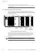
Communication 7.6.2 Entire Log – [Ctrl]+[P] This key sequence prints the entire Event History Log of the UPS at the time the data is requested. The printout begins with the oldest alarm entry in the queue and ends with the most recent. Any alarms that occur while the Event History Log is printing are included in chronological order. The Event History Log lists up to 400 system events in chronological order with the most recent event listed last. Figure 7-6 shows a sample Event History Log printout.
Communication 7.6.3 Meters Printout – [Ctrl]+[M] This key sequence prints the current readings of the UPS system meters. The input area shows the phase-to-phase voltage, frequency, and phase current of the incoming utility, followed by the kVA, kW, and power factor measurements. The output area shows the same information for the power being output by the UPS. The Bypass area shows the phase-to-phase voltage of the bypass source. The Battery area displays the DC voltage (V) and the DC current (I).
Communication 7.6.4 System Information Printout – [Ctrl]+[A] This key sequence prints a listing of all available serial data. This printout contains the information shown on the Event History Log and System Meters screens of the UPS (both Figure 7-6 and Figure 7-7). 7.6.5 Battery Test Printout – [Ctrl]+[B] This key sequence prints the Battery Test Log. The log consists of a history of the last 30 battery tests that were run and the results of those tests.
Communication 7.7 System Configuration The System Configuration mode allows you to modify special functions in your UPS. These functions include programming of building alarms, customizing building alarm messages, adjusting the nominal output voltage, and scheduling battery tests. The menus provided and their function are described in this section. 7.7.
Communication 7.7.3 Enable/Disable Default Functions From this menu you may either enable the building alarms for general functions or special functions such as On Generator, Go To Bypass, and Go To UPS. You may also customize the alarm messages from this menu. When 1 is selected from this menu, the following menu is displayed: Enable/Disable Default Functions 1. Enable/Disable Go To Bypass 2. Enable/Disable Go To UPS 3. Enable/Disable On Generator 4. Enable/Disable Building Alarm 5.
Communication 7.7.4 Customize Alarm Messages If Customize Alarm Messages is selected from the Program Building Alarm menu, you can select a custom message for a building alarm or disable a previously enabled building alarm custom message. When this entry is selected, the following menu is displayed: Customize Alarm Messages Enabled on Building Alarm Number(s) 2 3 Enter Building Alarm Number: This example indicates that there are custom messages enabled for Building Alarms 2 and 3.
Communication 7.7.5 Program Unit Name If Program Unit Name is selected from the main menu, the following is displayed: Program Unit Name Unit Name: Enter New Name or No Change: NOTE Unit Name is 45 characters maximum. The current unit name is displayed on the second line of the display and in the headers of prints from Terminal mode. If a change is desired, the new unit name should be entered at the prompt. The unit name is 45 characters maximum and includes spaces and any punctuation.
Communication 7.7.8 Battery Test Setup If Battery Test Setup is selected from the main menu, the following menu is displayed: Battery Test Setup 1. Setup One-time Delayed Battery Test 2. Setup Monthly Battery Test 3. Setup Quarterly Battery Test 4. Cancel Pending Battery Test 5. Display Next Scheduled Battery Test 6. Return to Main Menu Enter Selection: This menu allows you to schedule, review schedule, or cancel pending battery tests.
Communication 7.7.9 Modify Low Battery Time This menu allows you to modify the low battery time warning. When selected, the following menu is displayed: Modify Low Battery Time Low Battery Time (Minutes): 004 Enter New Low Battery Time: NOTE Low Battery Time should be no greater than 999. Press to return with no change. Enter the new time desired to change the warning level. 7.8 Calibration Mode Calibration mode is used by factory and field service personnel to calibrate system meters.
Communication 7.11 Remote Notification NOTE The X−Slot communication bay is connected internally to the DB−25 port by default; the DB−25 is disabled for other uses. Contact your Eaton service representative to purchase, install, and set up an external modem or an internal X−Slot Modem Card. NOTE Refer to the service documentation for detailed Remote Notification information. For connection and setup of a modem or to enable Remote Notify features within the UPS, please contact Powerware (see page 1−2).
Communication This page intentionally left blank. 7−20 EATON Powerware® 9315 UPS (200–300 kVA) Operation Manual S 164201036 Rev G www.powerware.
Chapter 8 Maintaining the UPS System WARNING Only qualified service personnel (such as a licensed electrician) should perform the battery installation and maintenance. Risk of electrical shock. The components inside the UPS cabinet are secured to a sturdy metal frame that is supported by the UPS magnetics. This design allows authorized service personnel to remove repairable components with very little disassembly.
Maintaining the UPS System WARNING A Do not dispose of the battery or batteries in a fire. Batteries may explode. Proper disposal of batteries is required. Refer to your local codes for disposal requirements. A Do not open or mutilate the battery or batteries. Released electrolyte is harmful to the skin and eyes. It may be toxic. CAUTION Do not discard the UPS or the UPS batteries in the trash. This product contains sealed, lead-acid batteries and must be disposed of properly.
Maintaining the UPS System ANNUAL maintenance − Annual preventive maintenance should be performed only by authorized service personnel familiar with maintenance and servicing of the UPS system. Contact your nearest field service office for more information about service offerings. BATTERY maintenance − Contact your nearest field service office for battery maintenance. Battery replacement and maintenance should be performed only by authorized service personnel. 8.
Maintaining the UPS System This page intentionally left blank. 8−4 EATON Powerware® 9315 UPS (200–300 kVA) Operation Manual S 164201036 Rev G www.powerware.
Chapter 9 Product Specifications The UPS systems are housed in freestanding, double-front cabinets with safety shields behind the doors. The UPS systems are available in 50/60 Hz with various output power ratings. Smaller models within a system may be upgraded in the field to larger models: Table 9-1.
Product Specifications Table 9-3. System Output Rectifier/Charger Capacity 125% DC Filtering Ripple voltage less than 0.
Product Specifications These specifications are for batteries supplied by the UPS manufacturer in line-up–and–match cabinets: Table 9-5. Battery Specifications Battery Type Sealed, maintenance-free, high rate discharge, lead-acid cells Nominal Battery String Voltage 480 Vdc (240 cells) for Powerware 9315 225 and Powerware 9315 300 420 Vdc (210 cells) for Powerware 9315 200 and Powerware 9315 250 Float Charging 2.
Product Specifications This page intentionally left blank. 9−4 EATON Powerware® 9315 UPS (200–300 kVA) Operation Manual S 164201036 Rev G www.powerware.
Chapter 10 Responding to System Events When the UPS system is running in Normal mode, it continually monitors itself and the incoming utility power. In Battery or Bypass modes, the UPS may issue alarms to let you know exactly what event caused the change from Normal mode. System events can be indicated by horns, lights on the UPS, or both. Select Active from the Events menu on the LCD screen to look at the Active System Events screen. This screen shows any currently active alarms, notices, or commands.
Responding to System Events INVERTER MESSAGES − ALARMS INVERTER MESSAGES − NOTICES Over Temperature Shutdown Battery Not Charged Clear Battery Not Charged 100% Overload Shutdown Bypass is Not Available Bypass is Available 125% Overload Shutdown Input Breaker Open Bypass Cont. (K2) Failure Inv. Logic Power Failure Clear Inv. Logic Pwr Fail. Bypass Cont.
Responding to System Events RECTIFIER MESSAGES − ALARMS RECTIFIER MESSAGES − NOTICES Rectifier DC Over Voltage Clear Rectifier DC Over Voltage Input AC Over Voltage Clear Input AC Over Voltage Rectifier DC Under Voltage Clear Rectifier DC Under Voltage Input AC Under Voltage Clear Input AC Under Voltage Rectifier Over Temperature Clear Rectifier Over Temperature Input AC Over Frequency Clear Input AC Over Frequency Rct. Over Temperature Warning Clear Rct. Over Temp.
Responding to System Events MONITOR PANEL ALARMS MONITOR PANEL NOTICES Load Over 100% Clear Load Over 100% Output AC Over Voltage Clear Output AC Over Voltage Overload 100% Clear Overload 100% Output AC Under Voltage Clear Output AC Under Voltage Overload 125% Clear Overload 125% Output Over Freq. Clear Output Over Freq. Power Supply Failure Clear Power Supply Fail.
Chapter 11 Using the LOAD OFF Button Load Off is initiated by the covered, red LOAD OFF button on the Monitor Panel. This button is protected by a clear plastic shield to prevent accidental activation. In an emergency, you can press this button to instantaneously open the input breaker and interrupt UPS output. The UPS is cut off from utility power, and the critical load is de-energized. All power to the critical load is lost.
Using the LOAD OFF Button 11.2 Resetting the UPS System after Load Off CAUTION Do not attempt to restart the system after Load Off until the cause of the emergency has been identified and cleared. The Load Off PUSH TO RESET button is a small white button on the UPS Control Panel. The PUSH TO RESET button pops out and the CB1 switch trips when the LOAD OFF button on the Monitor Panel is activated. To reset the UPS system: 1. Press the Load Off PUSH TO RESET button until it clicks in and remains recessed.
Warranty LIMITED FACTORY WARRANTY FOR THREE-PHASE POWERWARE® UPS PRODUCTS WARRANTOR: The warrantor for the limited warranties set forth herein is Eaton Electrical Inc., a Delaware Corporation ( Eaton"). LIMITED WARRANTY: This limited warranty (this Warranty") applies only to the original end−user (the End−User") of the Powerware Three−Phase UPS Products (the Product") and cannot be transferred. This Warranty applies even in the event that the Product is initially sold by Eaton for resale to an End−User.
Warranty This page intentionally left blank. W−2 EATON Powerware® 9315 UPS (200–300 kVA) Operation Manual S 164201036 Rev G www.powerware.
*164201036G* 164201036 G