
User Guide

INSTALLATION REFERENCE
EATON Powerware
®
9315 UPS (500–750 kVA) Installation and Operation Manual S 164201244 Rev E www.powerware.com
A-28
A.5 Customer Interface Wiring Notes
1. Use Class 1 wiring methods (as defined by the NEC) for control wiring. Install
the control wiring in separate conduit from the power wiring. The wire should
be rated at 24V, 1A minimum.
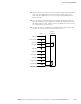
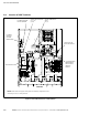
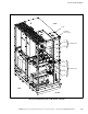
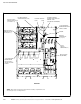
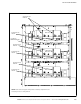
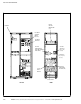
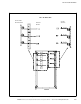
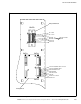
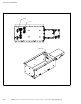
2. See Table O through Table Q and Figure A‐18 through Figure A‐30 for
customer interface wiring.
Table O. Input/Rectifier Cabinet Customer Interface Connections
CUSTJ4 Terminal Name Description
1
Open Filter
Dry contact used to deactivate input filter.
2 Open Filter Return
3 No Sync
Dry contact used to deactivate UPS synchronization to bypass.
4 No Sync Return
5 On Generator
Dry contact used to indicate UPS is being supplied power by the generator.
6 On Generator Return
7 Battery Disconnect Open
Dry contact used to indicate UPS Battery Disconnect is open.
8 Battery Disconnect Open Return
9 Not Used
10 Not Used
CB2TB Terminal Name Description
1 Not Used
2 CB2 Close - 120 Vac Close circuit breaker CB2 signal.
3 CB2 - AUX #1
Circuit breaker CB2 auxiliary contact.
4 CB2 - AUX #1
5 Not Used
6 Not Used
7 Control - 120 Vac
Breaker charge power.
8 Control - Neutral
9 Shunt Trip - 24 Vdc
Open circuit breaker CB2 signal.
10 Shunt Trip - 24 Vdc