Powerware® 9395 UPS 1000–1100 kVA Installation and Operation Manual For use with Three UPM (650–825 kVA) and Four UPM (1000–1100 kVA) UPS Models
IMPORTANT SAFETY INSTRUCTIONS SAVE THESE INSTRUCTIONS This manual contains important instructions that you should follow during installation and maintenance of the UPS and batteries. Please read all instructions before operating the equipment and save this manual for future reference.
Table of Contents 1 Introduction . . . . . . . . . . . . . . . . . . . . . . . . . . . . . . . . . . . . . . . . . . . . . . . . . . . . . . . . . . . . . . . . . . . . . . . . . . . 1.1 2 1−1 UPS Standard Features . . . . . . . . . . . . . . . . . . . . . . . . . . . . . . . . . . . . . . . . . . . . . . . . . . . . . . . . . . . . . . . . . . . . . . . . . . . . . . . . . 1.1.1 Installation Features . . . . . . . . . . . . . . . . . . . . . . . . . . . . . . . . . . . . . . . . . . . . . . . . . . .
TABLE OF CONTENTS 5 4.9 Installing Interface Connections . . . . . . . . . . . . . . . . . . . . . . . . . . . . . . . . . . . . . . . . . . . . . . . . . . . . . . . . . . . . . . . . . . . . . . . . . . . 4.9.1 TB1, TB2, and TB3 Connections (Other than TB1 Battery Interface Connections) . . . . . . . . . . . . . . . . . . . . . . . . . . . . . . . . . . . . . 4.9.2 TB1 Battery Interface Connections . . . . . . . . . . . . . . . . . . . . . . . . . . . . . . . . . . . . . . . . . . . . . . . . . . . . .
TABLE OF CONTENTS 8 9 7.3 Single UPS Operation . . . . . . . . . . . . . . . . . . . . . . . . . . . . . . . . . . . . . . . . . . . . . . . . . . . . . . . . . . . . . . . . . . . . . . . . . . . . . . . . . . 7.3.1 Starting the UPS in Normal Mode . . . . . . . . . . . . . . . . . . . . . . . . . . . . . . . . . . . . . . . . . . . . . . . . . . . . . . . . . . . . . . . . . . . . . 7.3.2 Starting the UPS in Bypass Mode . . . . . . . . . . . . . . . . . . . . . . . . . . . . . . . . . . . . . . . . . .
TABLE OF CONTENTS 10 Product Specifications . . . . . . . . . . . . . . . . . . . . . . . . . . . . . . . . . . . . . . . . . . . . . . . . . . . . . . . . . . . . . . . . . . 10−1 10.1 Model Numbers . . . . . . . . . . . . . . . . . . . . . . . . . . . . . . . . . . . . . . . . . . . . . . . . . . . . . . . . . . . . . . . . . . . . . . . . . . . . . . . . . . . . . . 10.2 Specifications . . . . . . . . . . . . . . . . . . . . . . . . . . . . . . . . . . . . . . . . . . . . . . . . . . . . . . . . . . .
TABLE OF CONTENTS List of Figures Figure 1-1. Powerware 9395 Four UPM UPS (1000–1100 kVA) . . . . . . . . . . . . . . . . . . . . . . . . . . . . . . . . . . . . . . . . . . . . . . . . . . . . Figure 1-2. Powerware 9395 Three UPM UPS (650–825 kVA) . . . . . . . . . . . . . . . . . . . . . . . . . . . . . . . . . . . . . . . . . . . . . . . . . . . . . Figure 3-1. UPS Cabinet Dimensions (Front View) . . . . . . . . . . . . . . . . . . . . . . . . . . . . . . . . . . . . . . . . . . . . . . . . . . . . . .
TABLE OF CONTENTS Figure 5-1. Powerware Hot Sync CAN Bridge Card . . . . . . . . . . . . . . . . . . . . . . . . . . . . . . . . . . . . . . . . . . . . . . . . . . . . . . . . . . . . . Figure 5-2. Powerware Hot Sync CAN Bridge Card Connections . . . . . . . . . . . . . . . . . . . . . . . . . . . . . . . . . . . . . . . . . . . . . . . . . . . Figure 5-3. Distributed Bypass System Can and Pull−Chain Simplified Interface Wiring . . . . . . . . . . . . . . . . . . . . . . . . . . . . . . . . . . .
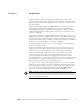
Chapter 1 Figure 1Table 1 Introduction Eaton’s Powerware® 9395 uninterruptible power supply (UPS) is a true online, continuous−duty, transformerless, double−conversion, solid−state, three−phase system, providing conditioned and uninterruptible AC power to protect the customer’s load from power failures.
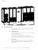
INTRODUCTION ISBM SECTION FI−UPM UPM SECTION Figure 1-1. Powerware 9395 Four UPM UPS (1000–1100 kVA) 1.1 UPS Standard Features The UPS has many standard features that provide cost-effective and consistently reliable power protection. The descriptions in this section provide a brief overview of the UPS standard features. 1.1.1 Installation Features Each UPS section is shipped separately. The sections are mechanically and electrically joined at the installation site.
INTRODUCTION ISBM SECTION UPM SECTION Figure 1-2. Powerware 9395 Three UPM UPS (650–825 kVA) 1.1.3 Customer Interface S Building Alarm Monitoring – Up to five inputs in the UPS are available to connect the facility’s alarm system contacts. Some system configurations may limit the number of inputs available. The UPS uses these inputs to monitor the building alarms in addition to the UPS status. See Chapter 8, Communication," for additional information.
INTRODUCTION 1.1.5 Power Management Software Powerware LanSafe® Power Management Software is bundled as part of the Software Suite CD shipped with the UPS. See Chapter 8, Communication," for additional information. 1.2 Options and Accessories Contact an Eaton sales representative for information about the following options. 1.2.1 Field Installed UPM A Field Installed UPM (FI−UPM) provides upgradability for the Powerware 9395 Three UPM UPS.
INTRODUCTION 1.2.4 Distributed Bypass System There are two types of redundancy: UPS based (based on the number of UPS units) and UPM based (based on the number of UPMs). Each UPS contains three or four UPMs. A distributed bypass UPS system with two to five UPS units can be installed to provide a capacity and/or redundant system. This load sharing system provides more capacity than a single UPS, and can provide backup, depending on the load and configuration.
INTRODUCTION 1.
INTRODUCTION 1.7 Symbols, Controls, and Indicators The following are examples of symbols used on the UPS or accessories to alert you to important information: RISK OF ELECTRIC SHOCK − Observe the warning associated with the risk of electric shock symbol. CAUTION: REFER TO OPERATOR’S MANUAL − Refer to your operator’s manual for additional information, such as important operating and maintenance instructions. This symbol indicates that you should not discard the UPS or the UPS batteries in the trash.
INTRODUCTION 1.
Chapter 2 Figure 2Table 2 Safety Warnings IMPORTANT SAFETY INSTRUCTIONS SAVE THESE INSTRUCTIONS This manual contains important instructions that should be followed during installation and maintenance of the UPS and batteries. Read all instructions before operating the equipment and save this manual for future reference. The UPS is designed for industrial or computer room applications, and contains safety shields behind the door and front panels.
SAFETY WARNINGS S The operating environment should be maintained within the parameters stated in this manual. S Keep surroundings uncluttered, clean, and free from excess moisture. S Observe all DANGER, CAUTION, and WARNING notices affixed to the inside and outside of the equipment. CAUTION To prevent damage to the wiring channel and wiring in the UPS cabinet base when lifting or moving the cabinet: S Lift and move the cabinet using only the front or rear forklift slots.
Section I Installation EATON Powerware® 9395 UPS (1000–1100 kVA) Installation and Operation Manual S 164201764 Rev 1 www.powerware.
2−2 EATON Powerware® 9395 UPS (1000–1100 kVA) Installation and Operation Manual S 164201764 Rev 1 www.powerware.
Chapter 3 Figure 3Table 3 UPS Installation Plan and Unpacking Use the following basic sequence of steps to install the UPS: 1. Create an installation plan for the UPS system (Chapter 3). 2. Prepare your site for the UPS system (Chapter 3). 3. Inspect and unpack the UPS sections (Chapter 3). 4. Unload and install the UPS sections, and wire the system (Chapter 4). 5. Install features, accessories, or options, as applicable (Chapter 5). 6. Complete the Installation Checklist (Chapter 4). 7.
UPS INSTALLATION PLAN AND UNPACKING For Field Installed UPM (FI−UPM) weights and dimensions, refe to the Powerware 9395 Field Installed UPM Mechanical Installation Manual, listed in paragraph 1.8 on page 1−7. Table 3-1.
UPS INSTALLATION PLAN AND UNPACKING Dimensions are in millimeters [inches]. Figure 3-1. UPS Cabinet Dimensions (Front View) Dimensions are in millimeters [inches]. Figure 3-2. UPS Cabinet Dimensions (Right Side View) EATON Powerware® 9395 UPS (1000–1100 kVA) Installation and Operation Manual S 164201764 Rev 1 www.powerware.
UPS INSTALLATION PLAN AND UNPACKING Figure 3-3. ISBM Section Dimensions (Front View) Figure 3-4. UPM Section Dimensions (Front View) 3−4 EATON Powerware® 9395 UPS (1000–1100 kVA) Installation and Operation Manual S 164201764 Rev 1 www.powerware.
UPS INSTALLATION PLAN AND UNPACKING Front Dimensions are in millimeters [inches]. Figure 3-5. ISBM Section Dimensions (Top View) Front Dimensions are in millimeters [inches]. Figure 3-6. ISBM Section Dimensions (Bottom View) Front Dimensions are in millimeters [inches]. Figure 3-7. UPM Section Dimensions (Top View) EATON Powerware® 9395 UPS (1000–1100 kVA) Installation and Operation Manual S 164201764 Rev 1 www.powerware.
UPS INSTALLATION PLAN AND UNPACKING CG CG Dimensions are in millimeters [inches]. Figure 3-8. ISBM Section Center of Gravity CG CG Dimensions are in millimeters [inches]. Figure 3-9. UPM Section Center of Gravity 3−6 EATON Powerware® 9395 UPS (1000–1100 kVA) Installation and Operation Manual S 164201764 Rev 1 www.powerware.
UPS INSTALLATION PLAN AND UNPACKING 0.87 [0.22] 115.8 [4.56] 88.9 [3.50] 114.3 [4.50] 95.3 [3.57] (Square) Front View 1.57 [0.40] Needed to remove key 1/2" Knockout Pattern (Typical 5 Sides) Dimensions are in millimeters [inches]. Figure 3-10. Remote EPO Switch Dimensions EATON Powerware® 9395 UPS (1000–1100 kVA) Installation and Operation Manual S 164201764 Rev 1 www.powerware.
UPS INSTALLATION PLAN AND UNPACKING 3.2.2 UPS System Power Wiring Preparation Read and understand the following notes while planning and performing the installation: S Refer to national and local electrical codes for acceptable external wiring practices. S To allow for future kVA upgrades, consider installing a derated UPS using wiring and external overcurrent protection breakers sized for a fully rated UPS.
UPS INSTALLATION PLAN AND UNPACKING For four UPM external wiring requirements, including the minimum AWG size of external wiring, see Table 3-4 for installations using a common battery system or Table 3-5 for installations using a separate battery system. Wire sizes listed are for copper wiring only.
UPS INSTALLATION PLAN AND UNPACKING Table 3-5.
UPS INSTALLATION PLAN AND UNPACKING Table 3-6. Input/Output Ratings and External Wiring Requirements for the Three UPM Powerware 9395−1100/650, 9395−1100/750, and 9395−1100/825 – Common Battery Units Rating 50/60 Hz Basic Unit Rating kVA kW 650 591 750 682 825 750 Input and Output Voltage Volts 480/480 480/480 480/480 Amps 891 1028 1130 AC Input to UPS Rectifier (0.
UPS INSTALLATION PLAN AND UNPACKING Table 3-7. Input/Output Ratings and External Wiring Requirements for the Three UPM Powerware 9395−1100/650, 9395−1100/750, and 9395−1100/825 – Separate Battery Units Rating 50/60 Hz Basic Unit Rating kVA kW 650 591 750 682 825 750 Input and Output Voltage Volts 480/480 480/480 480/480 Amps 891 1028 1130 AC Input to UPS Rectifier (0.
UPS INSTALLATION PLAN AND UNPACKING Table 3-8. UPS Intercabinet Power Cable Terminations for the Four UPM Powerware 9395−1100/1000 and 9395−1100/1100, and the Three UPM Powerware 9395−1100/650, 9395−1100/750, and 9395−1100/825 Terminal Function AC Input to UPM Section AC Output from UPM Section DC Input to UPM Section Terminal Function Bus Landing Tightening Torque Nm (lb ft) Stud E1A (UPM 1) E1A (UPM 2) E1A (UPM 3) E1A (UPM 4 – Four UPM Model) Phase A 3 – stud mounting 12 (8.
UPS INSTALLATION PLAN AND UNPACKING Terminals E1 through E12 are 2-hole busbar mountings for standard NEMA 2-hole barrel lugs. The power wiring connections for this equipment are rated at 90°C. See Table 3-10 for power cable terminations, Table 3-11 for supplied terminal hardware, and Table 3-12 for recommended installation parts and tools not supplied by Eaton Corporation. Figure 4-18 on page 4−21 and Figure 4-19 on page 4−22 show the location of the power cable terminals inside the UPS. Table 3-10.
UPS INSTALLATION PLAN AND UNPACKING Table 3-11.
UPS INSTALLATION PLAN AND UNPACKING Conduit sizes were chosen from NEC Table 4, Electrical Metallic Tubing (EMT). See Table 3-13 for conduit requirements. Per NEC article 300, 3(B)(1), all three-phase conductors must be run in the same conduit. Neutral and ground must be run in the same conduit as the phase conductors. Conduit is sized to accommodate one neutral conductor the same size as the phase conductor and one ground conductor sized in accordance with NEC Table 250.122.
UPS INSTALLATION PLAN AND UNPACKING External overcurrent protection and disconnect are not provided by this product, but are required by codes. Refer to Table 3-4, Table 3-5, Table 3-6, or Table 3-7 starting on page 3−9 for wiring requirements. If an output lockable disconnect is required, it is to be supplied by the customer. Table 3-14 lists the recommended rating for input circuit breakers. Table 3-14.
UPS INSTALLATION PLAN AND UNPACKING There is no manual DC disconnect device within the UPS. A battery disconnect switch is required for battery systems and may also be required by NEC or local codes. The battery disconnect switch should be installed between the battery and the UPS. External DC input overcurrent protection and disconnect switch is to be provided by the customer. Table 3-16 and Table 3-17 list the maximum ratings for continuous-duty rated circuit breakers satisfying the criteria for both.
UPS INSTALLATION PLAN AND UNPACKING 3.2.3 UPS System Interface Wiring Preparation Control wiring for features and options should be connected at the customer interface terminal blocks located inside the UPS. WARNING Do not directly connect relay contacts to the mains related circuits. Reinforced insulation to the mains is required. Read and understand the following notes while planning and performing the installation: S Use Class 1 wiring methods (as defined by the NEC) for interface wiring up to 30V.
UPS INSTALLATION PLAN AND UNPACKING S The REPO switch wiring must be in accordance with NEC Article 725 Class 2 requirements. S The maximum distance between the REPO and the UPS cannot exceed 150 meters (500 feet). S Alarm relay contacts have a maximum current rating of 5A and a switched voltage rating of 30 Vac and 28 Vdc. S Alarm relay wiring should be a minimum of 22 AWG. 3.2.
UPS INSTALLATION PLAN AND UNPACKING 3.3 Inspecting and Unpacking the UPS Cabinets The UPS cabinet is divided into two sections palleted separately for shipping. The sections are shipped bolted to wooden pallets (see Figure 3-11 and Figure 3-12) and protected with outer protective packaging material. WARNING The UPS sections are heavy (see Table 3-1 on page 3−2). If unpacking and unloading instructions are not closely followed, the cabinets may tip and cause serious injury.
UPS INSTALLATION PLAN AND UNPACKING 4. Remove the protective covering from the cabinets. 5. Remove the packing material, and discard or recycle in a responsible manner. 6. Inspect the contents for any evidence of physical damage, and compare each item with the Bill of Lading. If damage has occurred or shortages are evident, contact an Eaton service representative immediately to determine the extent of the damage and its impact on further installation.
UPS INSTALLATION PLAN AND UNPACKING Figure 3-12. UPS Cabinet as Shipped on Pallet (UPM Section) EATON Powerware® 9395 UPS (1000–1100 kVA) Installation and Operation Manual S 164201764 Rev 1 www.powerware.
UPS INSTALLATION PLAN AND UNPACKING This page intentionally left blank. 3−24 EATON Powerware® 9395 UPS (1000–1100 kVA) Installation and Operation Manual S 164201764 Rev 1 www.powerware.
Chapter 4 4.1 Figure 4Table 4 UPS System Installation Preliminary Installation Information WARNING Installation should be performed only by qualified personnel. Refer to the following while installing the UPS system: S Chapter 3 for cabinet dimensions, equipment weight, wiring and terminal data, and installation notes. S Do not tilt the cabinets more than "10° during installation. S Remove the conduit landing plates to add conduit landing holes as required. Plate material is 16 gauge steel (1.5 mm/0.
UPS SYSTEM INSTALLATION NOTE For the following steps, verify that the forklift or pallet jack is rated to handle the weight of the cabinet (see Table 3-1 on page 3−2 for cabinet weight). 1. If not already accomplished, use a forklift or pallet jack to move the ISBM and UPM sections to the installation area, or as close as possible, before unloading from the pallets. If possible, move each section using the pallet.
UPS SYSTEM INSTALLATION ISBM Removable Front Panels Pallet Shipping Bracket Bolts Right Side Shipping Bracket Shipping Bracket Bolts Figure 4-2. Removing the ISBM Section Right Side Shipping Bracket 4. Using a forklift (see the caution statement at the beginning of this procedure), raise the cabinet until the cabinet bottom clears the pallet by approximately 3 mm (1/8"). 5. Pull the pallet from under the cabinet. Discard or recycle the pallet and shipping brackets in a responsible manner. 6.
UPS SYSTEM INSTALLATION UPM Removable Front Panels Pallet Shipping Bracket Bolts Wireway Panel Shipping Bracket Bolts Left Side Shipping Bracket Figure 4-3. Removing the UPM Section Left Side Shipping Bracket 4−4 EATON Powerware® 9395 UPS (1000–1100 kVA) Installation and Operation Manual S 164201764 Rev 1 www.powerware.
UPS SYSTEM INSTALLATION Pallet Shipping Bracket Bolts Right Side Shipping Bracket Shipping Bracket Bolts Figure 4-4. Removing the UPM Section Right Side Shipping Bracket 4.3 Mechanically Joining the Sections NOTE The following procedure permits the UPS sections to be installed in a location where there is limited space to slide the sections together from the sides.
UPS SYSTEM INSTALLATION Left Top Panel Left Middle Panel Interior Left Side Panel Corner Channel UPM Section Wireway Panel Figure 4-5. Section Joining 5. Remove the screws securing the left top panel and remove the panel (see Figure 4-5). Retain the hardware for later use. 6. Remove the screws securing the left middle panel and remove the panel (see Figure 4-5). Retain the hardware for later use.
UPS SYSTEM INSTALLATION UPM Wireway (Power wiring harnesses are coiled in this area.) Figure 4-6. ISBM and UPM Sections Joined 10. Reinstall the left top panel (see Figure 4-5) and secure using the retained hardware. NOTE Three flat cabinet joining brackets are provided in the hardware kit for securing the ISBM and UPM sections at the top front, top rear, and front base (see Steps 11 and 12). 11. Locate the hardware kit (packed inside a drawstring bag tied to the left middle panel of the UPM section).
UPS SYSTEM INSTALLATION Screw from Kit Screw from Kit Screw from Kit Screw from Kit Back Bracket from Kit ISBM Section Top UPM Section Top Bracket from Kit ISBM Section Top UPM Section Top Front Top View Rear Bracket Top View Front Bracket Bracket from Kit UPM Section Base ISBM Section Base Front View Base Bracket Screw from Kit Screw from Kit Figure 4-7. ISBM Section to UPM Section Joining Brackets 4.4 Electrically Connecting the Sections 1.
UPS SYSTEM INSTALLATION NOTE Two cable lugs will be connected to each terminal stud. When connecting the cable lugs, install the first lug on the stud with the raised barrel portion facing the back of the cabinet. Install the second lug with the raised barrel portion facing the front of the cabinet. 6. Locate the intercabinet wiring terminal hardware kit packed on the bottom right side of the ISBM section. 7.
UPS SYSTEM INSTALLATION 13. Locate the ground braid in the bottom left front corner of the UPM section. The ground braid is secured at the factory to the UPM section ground bolt. Route the ground braid through the wiring access in the right side panel of the ISBM section to the ground bolt in the ISBM section. 14. Connect the ground braid to the ISBM section ground bolt and secure.
UPS SYSTEM INSTALLATION AC Input Breaker CB1 Phase A Phase B AC Output from UPMs (See Figure 4-11 for detail.) Phase C Neutral from UPMs (See Figure 4-11 for detail.) Phase C Phase B Phase A AC Input to UPMs (See Figure 4-9 for detail.) Bypass Breaker CB4 CB4 Charging Handle Route wiring harnesses in this area below the bypass breaker CB4 charging handle to provide operating clearance for the handle. DC Input to UPMs – (E5) (See Figure 4-10 for detail.
UPS SYSTEM INSTALLATION UPM 4 (FI−UPM) Four UPM Model UPM 1 Cable 1G1 & 1G2 Orange Phase A (E1A) UPM 2 Cable 2G1 & 2G2 Orange UPM 3 Cable 3G1 & 3G2 Orange Phase B (E2A) UPM 1 Cable 1G1 & 1G2 Brown UPM 2 Cable 2G1 & 2G2 Brown UPM 4 (FI−UPM) Four UPM Model UPM 3 Cable 3G1 & 3G2 Brown Phase B (E2A) UPM 4 (FI−UPM) Four UPM Model UPM 1 Cable 1G1 & 1G2 Yellow Phase C (E3A) UPM 2 Cable 2G1 & 2G2 Yellow UPM 3 Cable 3G1 & 3G2 Yellow AC Input to UPMs NOTE Two cable lugs will be connected to each terminal st
UPS SYSTEM INSTALLATION Cable 1G3 Red UPM 1 (1E4A) + – + – + – Cable 1G3 Black Cable 1G3 Red UPM 2 (2E4A) Cable 2G3 Red Cable 3G3 Red UPM 3 (3E4A) UPM 1 (1E5A) Cable 2G3 Black Cable 2G3 Red + DC Input to UPMs Cable 1G3 Black Cable 2G3 Black – DC Input to UPMs Cable 3G3 Black Cable 3G3 Black Cable 3G3 Red UPM 2 (2E5A) UPM 3 (3E5A) Figure 4-10.
UPS SYSTEM INSTALLATION Protective Cage Location of J50, J51, J61, and J70 Coiled Harnesses Wiring Access Location of P61 Harness Front Front UPM Wireway Location of P50, P51, and P70 Harnesses Location of RJ−45 Coiled CAN Cable A ISBM Section Right Side View B UPM Section Left Side View Figure 4-12. UPS Intercabinet Interface Harness Locations 4−14 EATON Powerware® 9395 UPS (1000–1100 kVA) Installation and Operation Manual S 164201764 Rev 1 www.powerware.
UPS SYSTEM INSTALLATION Pl1 Interface Board Front ISBM Section Right Side Inside View Figure 4-13. Pl1 Interface Board Location Pl1 Interface Board J39 Inverter CAN Connector Figure 4-14. J39 Location on Pl1 Interface Board EATON Powerware® 9395 UPS (1000–1100 kVA) Installation and Operation Manual S 164201764 Rev 1 www.powerware.
UPS SYSTEM INSTALLATION 4.5 Field Installed UPM Installation NOTE FI−UPM installation is not applicable to a three UPM model. If installing a four UPM model, install the FI−UPM using the instructions in the Powerware 9395 Field Installed UPM Mechanical Installation Manual, listed in paragraph 1.8 on page 1−7. After the FI−UPM is installed, proceed to paragraph 4.6 if installing a battery system; otherwise, proceed to paragraph 4.7 to complete the wiring of the UPS. 4.
UPS SYSTEM INSTALLATION Ventilation Grill Debris Shield (Remove shield before operating system.) ISBM Section Front Ventilation Grill Debris Shields (Remove shields before operating system.) UPM Section Front Figure 4-15. ISBM and UPM Section Debris Shields EATON Powerware® 9395 UPS (1000–1100 kVA) Installation and Operation Manual S 164201764 Rev 1 www.powerware.
UPS SYSTEM INSTALLATION Top Entry Conduit Landing for AC Input and Output, and DC Input (Remove panel to drill or punch conduit holes.) TOP VIEW Front Interface Entry Conduit Landings for TB1 through TB3 Wiring and X−Slot Connections (Remove panels to drill or punch conduit holes.) Front BOTTOM VIEW Bottom Entry Conduit Landing for AC Input and Output, and DC Input (Remove panel to drill or punch conduit holes.) Figure 4-16.
UPS SYSTEM INSTALLATION 3. Route the input and output cables through either the top or bottom of the cabinet to the UPS terminals. See Figure 4-16 through Figure 4-19 for wiring access information and terminal locations. Top Access Wiring. Remove the top conduit plate from the top of the ISBM section. Identify all conduit requirements and mark their location. Drill and punch all conduit holes in the top conduit plate prior to mounting on the ISBM section.
UPS SYSTEM INSTALLATION UPS 1 Bypass Input to UPS Units 1A 2A Battery UPS 2 3A 4A Battery UPS 3 Output from UPS Units 1B Battery 2B UPS 4 3B 4B Battery NOTE Required parallel system wiring length must be equal to ensure approximately equal current sharing when in Bypass mode. For proper operation the following must be true: 1A = 2A = 3A = 4A 1B = 2B = 3B = 4B NOTE Any difference in wire length will result in decreased capacity of the UPS system while on bypass.
UPS SYSTEM INSTALLATION AC Input to UPS Rectifier (A, B, C) (See Figure 4-19 for Detail AA.) AC Input to UPS Bypass (A, B, C) (See Figure 4-19 for Detail AA.) Phase C (E11) AC Output to Critical Load Phase B (E10) Phase A (E9) DC Input from Battery + (E4) (See Figure 4-20 or Figure 4-21 for Detail BB.) A B C DC Input from Battery – (E5) (See Figure 4-20 or Figure 4-21 for Detail BB.) N Neutral (E12) ISBM Figure 4-18.
UPS SYSTEM INSTALLATION Ground Terminals Front ‘ Phase C (E3) Phase B (E2) AC Input to UPS Rectifier Phase A (E1) Phase A (E6) Phase B (E7) Phase C (E8) Section A–A Figure 4-19. ISBM Section Power Terminal Detail AA 4−22 EATON Powerware® 9395 UPS (1000–1100 kVA) Installation and Operation Manual S 164201764 Rev 1 www.powerware.
UPS SYSTEM INSTALLATION 4.8.2 Battery Power Wiring CAUTION When sizing the battery system, do not exceed the internal battery charger capabilities. See Chapter 10, Product Specifications," for maximum battery charger currents. To install wiring to connections: NOTE An installed FI−UPM is always designated as UPM 4. 1. Route the battery cables between the ISBM section and the battery system or battery disconnect.
UPS SYSTEM INSTALLATION DC Input from Battery + (E4) Front DC Input from Battery – (E5) Section B–B Figure 4-20. ISBM Section Power Terminal Detail BB – Common Battery 4−24 EATON Powerware® 9395 UPS (1000–1100 kVA) Installation and Operation Manual S 164201764 Rev 1 www.powerware.
UPS SYSTEM INSTALLATION DC Input from Battery + (E4) (UPM 3) DC Input from Battery + (E4) (UPM 2) DC Input from Battery + (E4) (UPM 1) DC Input from Battery + (E4) (UPM 4 – FI−UPM) Front DC Input from Battery – (E5) (UPM 4 – FI−UPM) DC Input from Battery – (E5) (UPM 1) DC Input from Battery – (E5) (UPM 2) DC Input from Battery – (E5) (UPM 3) Section B–B Figure 4-21.
UPS SYSTEM INSTALLATION 4.9 Installing Interface Connections WARNING Hazardous voltages are present near the user interface terminal area if the UPS is not totally disconnected. Use the procedures in the following paragraphs to connect the TB1, TB1 Battery, TB2, and TB3 interface connections. 4.9.
UPS SYSTEM INSTALLATION 11. Reinstall the front door removed in Step 3 and secure with the retained hardware. 12. Close the door and secure the latch. TB1 and TB2 (See Figure 4-23 for detail.) X−Slot Communication Bays (See Figure 4-28 on page 4−33 for detail.) TB3 (See Figure 4-25 on page 4−30 for terminal assignments.) ISBM Figure 4-22. ISBM Section Interface Terminal Locations EATON Powerware® 9395 UPS (1000–1100 kVA) Installation and Operation Manual S 164201764 Rev 1 www.powerware.
UPS SYSTEM INSTALLATION Table 4-1.
UPS SYSTEM INSTALLATION X−Slot Communication Bays TB1 See Figure 4-25 for terminal assignments. TB2 Figure 4-23. Interface Terminal Detail TB2 3 Alarm Relay NC 4 Alarm Relay Common 5 Alarm Relay NO 6 Alarm Relay Common Alarm Relay NOTE Alarm relay contacts have a maximum current rating of 5A and a switched voltage rating of 30 Vac and 28 Vdc. NOTE Alarm relay normally−open and normally−closed return terminals are separated on the terminal board but are electrically in common.
UPS SYSTEM INSTALLATION UPS REPO NC REPO Return REPO NO REPO Return 1 Battery Aux Battery Aux Common Battery Shunt Trip + Battery Shunt Trip – Output Contactor K3 NC Aux Output Contactor K3 NC Aux Common TB1 10 1 Pull Chain Pull Chain Common Alarm Relay NC Alarm Relay Common Alarm Relay NO Alarm Relay Common TB2 10 UPS 1 TB3 10 Building Alarm 1 Building Alarm 1 Return Building Alarm 2 Building Alarm 2 Return Building Alarm 3 Building Alarm 3 Return Building Alarm 4 Building Alarm 4 Return Build
UPS SYSTEM INSTALLATION 4.9.2 TB1 Battery Interface Connections To install wiring to connections: 1. Verify the UPS system is turned off and all power sources are removed. See Chapter 7, UPS Operating Instructions," for shutdown instructions. 2. Unfasten the front door latch and swing the door open (see Figure 4-1 on page 4−2). 3. Remove the door. Remove the retaining screw located inside the door at the bottom hinge pivot point, then lift the door off. Retain the hardware for later use. 4.
UPS SYSTEM INSTALLATION Battery Disconnect UPS TB1 Battery Aux 5 Battery Aux Common 6 48 Vdc Battery Shunt Trip + 7 48 Vdc 48 Vdc Battery Shunt Trip – ST 8 NOTE Battery aux and DC shunt trip wiring should be a minimum of 18 AWG. Figure 4-26.
UPS SYSTEM INSTALLATION 4.9.3 X−Slot Connections NOTE LAN and telephone drops for use with X−Slot cards must be provided by the customer. NOTE When installing external wiring to X−Slot cards, conduit must be installed to the UPS cabinet. When installing internal wiring to X−Slot terminals, route the wiring through the internal opening in the X−Slot communication bay. For installation and setup of an X−Slot card, contact an Eaton service representative (see page 1−8). To install wiring to connections: 1.
UPS SYSTEM INSTALLATION 4.10 Installing a REPO Switch A latching−type Remote Emergency Power−off (REPO) switch can be used in an emergency to shut down the UPS and remove power to the critical load from a location away from where the UPS is installed. Figure 4-29 shows a REPO switch. NOTE Before installing a REPO switch, verify that the UPS was installed according to the instructions in paragraphs 4.2 through 4.9.
UPS SYSTEM INSTALLATION 5. To gain access to terminal block TB1 and the interface entry conduit landing plate, remove the screws securing the top internal safety shield panel and remove the panel. Retain the hardware for later use (see Figure 4-22 on page 4−27). 6. Remove the left interface entry conduit landing plate to drill or punch holes (see Figure 4-16 on page 4−18). 7. Reinstall the interface entry plate and install conduit. 8.
UPS SYSTEM INSTALLATION 12. If required, install wiring from the REPO switch to the trip circuitry of the upstream protective devices. A second contact block is provided on the REPO switch for this function (see Figure 4-29). The REPO switch wiring must be in accordance with NEC Article 725 Class 2 requirements. 13. Reinstall the top internal safety shield panel and secure with the retained hardware. 14. Reinstall the front door removed in Step 4 and secure with the retained hardware. 15.
UPS SYSTEM INSTALLATION 1 (NC) REPO Switch (NC) 2 (Return) UPS TB1 3 (NO) REPO Switch (NO) Twisted Wires 4 (Return) NOTE REPO switch rating is 24 Vdc, 1A minimum. NOTE The REPO switch must be a latching−type switch not tied to any other circuits. NOTE REPO normally−open and normally−closed return terminals are separated on the terminal board but are electrically in common. Figure 4-32. Normally-Closed and Normally-Open REPO Switch Wiring 4.
UPS SYSTEM INSTALLATION Installation Checklist - All packing materials and restraints have been removed from each cabinet. - Each cabinet in the UPS system is placed in its installed location. - Joining brackets are installed between the ISBM and UPM sections. - Intercabinet power wiring is installed between the ISBM and UPM sections. - Intercabinet interface wiring is installed between the ISBM and UPM sections. - A cabinet grounding/mounting kit is installed between the ISBM and UPM sections.
UPS SYSTEM INSTALLATION Distributed Bypass Installation Checklist - Each cabinet in the distributed bypass system is placed in its installed location. - All conduits and cables are properly routed to the UPS cabinets and to the tie cabinet or distribution panel. - All power cables are properly sized and terminated. - Neutral conductors are installed or bonded to ground as per requirements. - A ground conductor is properly installed.
UPS SYSTEM INSTALLATION Notes _________________________________________________________________________ _________________________________________________________________________ _________________________________________________________________________ _________________________________________________________________________ _________________________________________________________________________ _________________________________________________________________________ _____________________________________
Chapter 5 5.1 Figure 5Table 5 Installing Options and Accessories Installing an Optional Powerware Hot Sync CAN Bridge Card As an option, a Powerware Hot Sync Controller Area Network (CAN) Bridge Card, shown in Figure 5-1, can be installed to provide connectivity for operational mode control of a parallel system. In addition, this card can be used to connect optional system monitoring devices, such as a Remote Monitor Panel II, a Relay Interface Module II, or a Supervisory Contact Module II to the UPS.
INSTALLING OPTIONS AND ACCESSORIES 4. Read and understand the following notes while planning and performing the wiring installation: S Conduit must be installed between the UPS cabinet and the device for signal wiring. Conduit must be installed between the device and the power source for power wiring. Install the signal wiring in separate conduit from the power wiring. S Conduit and wiring between the UPS and the device are to be supplied by the customer.
INSTALLING OPTIONS AND ACCESSORIES J3 Connections for Parallel System Control Connections for RMP II, RIM II, or SCM II Connections for Bypass Status Alarm Figure 5-2. Powerware Hot Sync CAN Bridge Card Connections Table 5-1. Powerware Hot Sync CAN Bridge Card Interface Connections J3 Terminal Name Description 1 Alarm 2 Alarm Return 3 Alarm Relay NC Normally-closed contact opens when UPS is on bypass. 4 Alarm Relay Com Bypass contact return.
INSTALLING OPTIONS AND ACCESSORIES 5.2 Installing Distributed Bypass Control Wiring NOTE When installing external wiring to the Powerware Hot Sync CAN Bridge Card, conduit must be installed to the UPS cabinet. When installing internal wiring to the Powerware Hot Sync CAN Bridge Card terminals, route the wiring through the internal opening in the X−Slot communication bay. NOTE When installing interface wiring for the parallel system pull chain, conduit must be installed between UPSs.
INSTALLING OPTIONS AND ACCESSORIES CAN Pull Chain UPS 1 UPS 2 UPS 3 UPS 4 (If Installed) (If Installed) NOTE This drawing is for distributed bypass wiring purposes and is not a floor layout plan. UPSs can be placed in any physical order. Figure 5-3.
INSTALLING OPTIONS AND ACCESSORIES Twisted Pair Twisted Pair Twisted Pair TB1 TB1 TB1 TB1 1 1 1 1 2 2 2 2 3 3 3 3 4 4 4 4 5 5 5 5 6 6 6 6 7 7 7 7 8 8 8 8 9 9 9 9 10 10 10 10 TB2 TB2 TB2 TB2 1 1 1 1 2 2 2 2 3 3 3 3 4 Twisted Pair 5 4 4 Twisted Pair Twisted Pair 4 Twisted Pair 5 5 5 6 6 6 6 7 7 7 7 8 8 8 8 9 9 9 9 10 10 10 10 UPS 3 (If Installed) UPS 4 (If Installed) UPS 1 UPS 2 NOTE Use twisted pair wiring bet
INSTALLING OPTIONS AND ACCESSORIES Shielded Twisted Pair Shielded Twisted Pair Twisted Pair UPS 1 CAN Bridge Card J3 Twisted Pair UPS 2 CAN Bridge Card J3 MOB 2 NC NC NO NC NO COM AUX 1 COM AUX 2 NO Twisted Pair UPS 4 CAN Bridge Card J3 (If Installed) Customer−Supplied Tie Cabinet MOB 3 COM AUX 1 COM AUX 2 NC NO NC TB1 NO MOB 4 COM AUX 1 COM AUX 2 TB1 7 7 8 8 8 8 9 9 9 9 10 10 10 10 TB2 1 1 2 2 2 2 3 3 3 3 4 4 4 4 5 5 5 5 6 6 6 6 7 7 7 7 8
INSTALLING OPTIONS AND ACCESSORIES Table 5-4.
INSTALLING OPTIONS AND ACCESSORIES 5.3 Installing an Optional Remote Monitor Panel II To install RMP II wiring: 1. Verify the UPS system is turned off and all power sources are removed. See Chapter 7, UPS Operating Instructions," for shutdown instructions. 2. Perform the procedure listed in paragraph 5.1. NOTE If mounting to a hollow wall, secure the enclosure to a wood or metal stud within the wall. Do not use hollow wall anchors. 3. Securely mount the RMP II at the desired location.
INSTALLING OPTIONS AND ACCESSORIES Ground Terminal Terminal TB1 Signal Connections from the UPS Terminal TB3 120 Vac Power Figure 5-7. Remote Monitor Panel II and Relay Interface Module II Terminal Locations Ground Terminal Neutral 120 Vac from Critical Bus Line UPS Can Card J3 RMP II, RIM II, or SCM II Twisted Pair Figure 5-8. Remote Monitor Panel II, Relay Interface Module II, or Supervisory Contact Module II Wiring Table 5-5.
INSTALLING OPTIONS AND ACCESSORIES NOTE Setup of the Powerware Hot Sync CAN Bridge Card must be performed by an authorized Eaton Customer Service Engineer. Contact an Eaton service representative to schedule a date. 11. To check the operation of the RMP II, ensure that the UPS is supplying the load via inverter or bypass. If the indicators on the RMP II show the appropriate status, then it is operating correctly.
INSTALLING OPTIONS AND ACCESSORIES 10. Restart the UPS. See Chapter 7, UPS Operating Instructions," for startup instructions. NOTE Setup of the Powerware Hot Sync CAN Bridge Card must be performed by an authorized Eaton Customer Service Engineer. Contact an Eaton service representative to schedule a date. 11. Contact an Eaton service representative for verification and testing of the RIM II and its connections prior to making connections with J1 through J4 (see Table 5-6 and Figure 5-9).
INSTALLING OPTIONS AND ACCESSORIES 5.5 Installing an Optional Supervisory Contact Module II To install SCM II wiring: 1. Verify the UPS system is turned off and all power sources are removed. See Chapter 7, UPS Operating Instructions," for shutdown instructions. 2. Perform the procedure listed in paragraph 5.1 on page 5−1. NOTE If mounting to a hollow wall, secure the enclosure to a wood or metal stud within the wall. Do not use hollow wall anchors. 3.
INSTALLING OPTIONS AND ACCESSORIES NOTE Setup of the Powerware Hot Sync CAN Bridge Card must be performed by an authorized Eaton Customer Service Engineer. Contact an Eaton service representative to schedule a date. 9. Install wiring between the SCM II terminal block TB2 and the monitoring equipment. See Figure 5-10 for terminal block location and Figure 5-11 for terminal assignments. 10. Close the front door and secure the latch. 11. Restart the UPS.
INSTALLING OPTIONS AND ACCESSORIES 5.6 Accessory Mounting Dimensions Figure 5-12 through Figure 5-14 show the dimensions of the RMP II, the RIM II, and the SCM II. Knockouts Provided on Five Surfaces Flush Mount using #10 Pan Head Screws. (Mount with vent holes facing up.) Surface Mount using #10 Pan Head Screws for Hanging. (Mount with vent holes facing up.) Dimensions are in millimeters [inches]. Figure 5-12.
INSTALLING OPTIONS AND ACCESSORIES Knockouts Provided on Five Surfaces Flush Mount using #10 Pan Head Screws. (Mount with vent holes facing up.) Surface Mount using #10 Pan Head Screws for Hanging. (Mount with vent holes facing up.) Dimensions are in millimeters [inches]. Figure 5-13. Relay Interface Module II Dimensions 5−16 EATON Powerware® 9395 UPS (1000–1100 kVA) Installation and Operation Manual S 164201764 Rev 1 www.powerware.
INSTALLING OPTIONS AND ACCESSORIES Knockouts Provided on Five Surfaces Flush Mount using #10 Pan Head Screws. (Mount with vent holes facing up.) Surface Mount using #10 Pan Head Screws for Hanging. (Mount with vent holes facing up.) Dimensions are in millimeters [inches]. Figure 5-14. Supervisory Contact Module II Dimensions EATON Powerware® 9395 UPS (1000–1100 kVA) Installation and Operation Manual S 164201764 Rev 1 www.powerware.
INSTALLING OPTIONS AND ACCESSORIES This page intentionally left blank. 5−18 EATON Powerware® 9395 UPS (1000–1100 kVA) Installation and Operation Manual S 164201764 Rev 1 www.powerware.
Section II Operation EATON Powerware® 9395 UPS (1000–1100 kVA) Installation and Operation Manual S 164201764 Rev 1 www.powerware.
5−20 EATON Powerware® 9395 UPS (1000–1100 kVA) Installation and Operation Manual S 164201764 Rev 1 www.powerware.
Chapter 6 6.1 Understanding UPS Operation Figure 6Table 6 UPS System Overview The Powerware 9395 UPS is a continuous−duty, solid-state, transformerless (at 480 Vac), three−phase, true online system that provides conditioned and uninterruptible AC power to the UPS system’s output and critical load. The basic system consists of a rectifier, battery converter, inverter, monitoring/operation control panel, integrated communication server, and digital signal processor (DSP) logic.
UNDERSTANDING UPS OPERATION 6.2 Single UPS A single UPS operates independently to support an applied load from the inverter, providing conditioned and uninterruptible AC power to the critical load from the output of the module. During an outage, the inverter continues to operate, supporting power to the load from the battery supply. If the unit requires service, applied loads are transferred to the internal bypass, continuous−duty static switch either automatically or manually.
UNDERSTANDING UPS OPERATION Bypass Breaker (CB4) Static Bypass Input Rectifier Input Input Breaker (CB1 K5 Switch Rectifier Output Inverter K1 K3 Battery Converter Main Power Flow Breakers K2 Contactors Closed Battery Breaker Trickle Current Battery Breaker Energized Open De−Energized Battery Figure 6-2. Path of Current Through the UPS in Normal Mode If the UPS becomes overloaded or unavailable, the UPS switches to Bypass mode.
UNDERSTANDING UPS OPERATION The internal bypass is comprised of a solid−state, silicon−controlled rectifier (SCR) static switch (SSW), a motorized wraparound bypass breaker CB4, and a backfeed protection contactor K5. The static switch is rated as a momentary−duty device that is used instantaneously anytime the inverter is unable to support the applied load. The static switch is wired in series with the backfeed protection contactor, and CB4 is wired in parallel with this combination.
UNDERSTANDING UPS OPERATION During a utility power failure, the rectifier no longer has an AC utility source from which to supply the DC output current required to support the inverter. The input contactor K1 opens and the battery instantaneously supplies energy to the battery converter. The converter either bucks or boosts the voltage so that the inverter can support the customer’s load without interruption. If bypass is common with the rectifier input, the backfeed protection contactor K5 also opens.
UNDERSTANDING UPS OPERATION 6.3 Single UPS Unit System Oneline Configurations The system oneline drawings in this section show the simplified internal structure of the UPS, battery supply, and basic maintenance bypass.
UNDERSTANDING UPS OPERATION AC Input to Bypass 3 or 4 Wire A−B−C Rotation AC Input to UPS Rectifier 3 Wire A−B−C Rotation B A E1, E2, E3 Rectifier X−Slot Interface Remote EPO Input Contactor (K1) Rectifier Fuse Fuse Fuse Fuse Fuse Fuse Inverter Backfeed Contactor (K5) Rectifier Fuse Fuse Inverter Output Contactor (K3) Alarm Relays Input Contactor (K1) Rectifier Fuse Battery Converter Static Switch Input Contactor (K1) Fuse 48V Battery Shunt Trip Interface Board Fuse Input Con
UNDERSTANDING UPS OPERATION AC Input to Bypass 3 or 4 Wire A−B−C Rotation AC Input to UPS Rectifier 3 Wire A−B−C Rotation B A E1, E2, E3 Static Switch Input Contactor (K1) Rectifier Fuse Fuse Inverter Input Contactor (K1) Rectifier Fuse Fuse Fuse Inverter Fuse Inverter Output Contactor (K3) Battery Converter Backfeed Contactor (K5) Fuse Fuse Output Contactor (K3) X−Slot Interface Remote EPO Rectifier Fuse Fuse Alarm Relays Input Contactor (K1) Rectifier Fuse 48V Battery Shunt
UNDERSTANDING UPS OPERATION AC Input to Bypass 3 or 4 Wire A−B−C Rotation AC Input to UPS Rectifier 3 Wire A−B−C Rotation Bypass Breaker (CB4) B A E1, E2, E3 Battery Aux Building Alarms 48V Battery Shunt Trip Alarm Relays X−Slot Interface Remote EPO E6, E7, E8, E12 Input Breaker (CB1) (optional) Interface Board Static Switch Fuse Input Contactor (K1) Backfeed Contactor (K5) Input Contactor (K1) Rectifier Input Contactor (K1) Rectifier Fuse Rectifier Fuse Fuse Fuse Fuse Fuse Fuse
UNDERSTANDING UPS OPERATION AC Input to Bypass 3 or 4 Wire A−B−C Rotation AC Input to UPS Rectifier 3 Wire A−B−C Rotation Bypass Breaker (CB4) B A E1, E2, E3 Battery Aux Building Alarms 48V Battery Shunt Trip Alarm Relays X−Slot Interface Remote EPO E6, E7, E8, E12 Input Breaker (CB1) (optional) Interface Board Static Switch Fuse Input Contactor (K1) Input Contactor (K1) Rectifier Input Contactor (K1) Rectifier Fuse Fuse Backfeed Contactor (K5) Rectifier Fuse Fuse Fuse Fuse Fuse Fu
UNDERSTANDING UPS OPERATION To UPS Rectifier Input AC Input To UPS Bypass Input AC Input RIB MBP BIB MIS CRITICAL LOAD DISTRIBUTION UNIT Output from UPS MAINTENANCE BYPASS PANEL (Provided by Others) Backfeed Contactor Static Switch K5 Output Contactor K3 UPS Battery Breaker BATTERY SYSTEM RIB: BIB: MIS: MBP: Rectifier Input Breaker Bypass Input Breaker Maintenance Isolation Breaker Maintenance Bypass Breaker NOTE If installing a maintenance bypass, a minimum of two separate feeds with ups
UNDERSTANDING UPS OPERATION 6.4 Multiple UPS Distributed Bypass System Distributed bypass parallel operation extends the normal operation of Powerware 9395 UPSs by offering increased capacity and/or redundant capability. The parallel system continues to maintain power to the critical loads during commercial electrical power brownout, blackout, overvoltage, undervoltage, and out-of-tolerance frequency conditions.
UNDERSTANDING UPS OPERATION The UPSs continually monitor themselves and the incoming utility power and automatically switch between these modes as required, without operator intervention, except when manually switching to Bypass mode. The sophisticated detection and switching logic inside the UPSs ensures that operating mode changes are automatic and transparent to the critical load, while internal monitoring systems indicate the current mode of operation.
UNDERSTANDING UPS OPERATION If the utility AC power is interrupted or is out of specification, the UPSs automatically switch to Battery mode to support the critical load without interruption. When utility power returns, the UPSs return to Normal mode. If the UPSs become overloaded or unavailable, the distributed bypass system switches to Bypass mode.
UNDERSTANDING UPS OPERATION In a distributed bypass system, each UPS operates similar to a single UPS, but in parallel with each other. The bypass source for the load is derived from the bypass input of one, two, three, or four UPSs, depending on the system configuration, through the internal static switches. If a module is taken offline, the other modules remain online to support the load.
UNDERSTANDING UPS OPERATION Bypass Input UPS Input Tie Cabinet UPS 1 Output UPS 1 Battery UPS 2 Output UPS 2 Battery UPS 3 Output UPS 3 Battery UPS 4 Output UPS 4 Battery Breakers Closed Main Power Flow Open Output to Critical Load Figure 6-12. Path of Current through the UPSs in Battery Mode – Distributed Bypass If at any time during the battery discharge the input power becomes available again, the rectifier begins to supply DC current to the inverter. At this point, the UPS returns to Normal mode.
UNDERSTANDING UPS OPERATION 6.5 Multiple UPS Distributed Bypass System Oneline Configurations The distributed bypass system oneline drawings in this section show the simplified internal structure of the UPS, battery supply, and basic maintenance bypass in a multiple UPS configuration. These onelines do not show each UPM in the UPSs, but represent each UPS in the distributed bypass system. The internal structure of each UPS is shown in Figure 6-5 through Figure 6-8 starting on page 6−7.
UNDERSTANDING UPS OPERATION A B * A * E1 E2 E3 B * * E6 E7 E8 E12 UPS 2 Fuse CB1 (optional) E1 E2 E3 Fuse CB1 (optional) K1 K1 CB4 CB4 Rectifier Rectifier Static Switch Static Switch Fuse Fuse K5 K5 Fuse Fuse Fuse Fuse Inverter Inverter K3 K3 Battery Converter Battery Converter Fuse Fuse K2 C K2 C E4. E5 E4.
UNDERSTANDING UPS OPERATION A B * A * E1 E2 E3 B * E6 E7 E8 E12 UPS 3 Fuse CB1 (optional) * E1 E2 E3 E6 E7 E8 E12 UPS 2 Fuse * E1 E2 E3 Fuse K1 CB4 Rectifier CB4 Rectifier Static Switch Rectifier Static Switch Fuse Static Switch Fuse Fuse K5 K5 Fuse K5 Fuse Fuse Fuse Fuse Inverter Fuse Inverter K3 Inverter K3 Battery Converter K3 Battery Converter Battery Converter Fuse Fuse K2 Battery Breaker BATTERY SYSTEM (Not supplied with the UPS) D Fuse K2 C E4.
UNDERSTANDING UPS OPERATION A B * A * E1 E2 E3 B * E6 E7 E8 E12 UPS 4 Fuse CB1 (optional) * E1 E2 E3 Fuse E1 E2 E3 Fuse CB1 (optional) Fuse Fuse Inverter Inverter K3 K3 Battery Converter Fuse Battery Converter Fuse K2 Fuse K2 C Battery Breaker BATTERY SYSTEM (Not supplied with the UPS) D Fuse K2 C E4. E5 Battery Breaker (Not supplied with the UPS) Fuse Fuse Battery Converter E9, E10, E11, E12 K5 Fuse K3 BATTERY SYSTEM Static Switch K5 Inverter E4.
Chapter 7 Figure 7Table 7 UPS Operating Instructions This section describes how to operate the UPS. NOTE Before starting the UPS, ensure all installation tasks are complete and a preliminary startup has been performed by authorized service personnel. The preliminary startup verifies all electrical interconnections to ensure the installation was successful and the system operates properly.
UPS OPERATING INSTRUCTIONS 7.1.1 Control Panel The control panel is used to set up and control the UPS, and to monitor UPS operation. For a description of the UPS control panel functions, see paragraph 7.2. 7.1.2 Circuit Breaker Optional circuit breaker (CB1) is used to control the AC input to the UPS rectifier. NOTE CB1 is supplied with an extension handle to assist in operating the breaker. This handle can not be installed permanently and must be removed for the front door to close.
UPS OPERATING INSTRUCTIONS 7.2.1 Status Indicators The four symbols on the right side of the control panel are status indicators. These colored light emitting diode (LED) lamps, work with the alarm horn to let you know the operating status of the UPS. Table 7-1 describes the status indicators. Table 7-1. Status Indicators Indicator Green Status Description On The UPS is operating normally. The power module is supplying power to the critical load. Off The UPS is turned off.
UPS OPERATING INSTRUCTIONS 7.2.3 Using the LCD and Pushbuttons The LCD on the control panel provides an operator interface with the UPS system. Figure 7-3 identifies the display areas discussed in the following sections. A B C ALARM: INPUT INPUT AC UNDER VOLTAGE UPS BATT BYPASS EVENTS STSW METERS CONTROLS SETUP OUTPUT LOAD OFF D Figure 7-3.
UPS OPERATING INSTRUCTIONS 7.2.4 Using the Menu The UPS menu bar allows you to display data in the information area to help you monitor and control UPS operation. Table 7-2 shows the basic menu structure. Table 7-2. Display Function Menu Map Menu Option Description EVENTS Displays the list of Active System Events and a historical log of system events. METERS Displays performance meters for the system or critical load. CONTROLS SETUP Displays the System Status screen.
UPS OPERATING INSTRUCTIONS 7.2.6 Display Menu Operation Table 7-3 describes the menu functions and and how to use them. Table 7-3. Display Menu Operation Function Subfunction Operation Events Press the EVENTS pushbutton on the main menu bar or History menu bar to display a listing of all system events that are currently active. The most recent event is listed first. As events clear, they are removed from the Active System Events listing.
UPS OPERATING INSTRUCTIONS Table 7-3. Display Menu Operation (continued) Function System Level 1 Setup Subfunction Operation Contrast Adjust Select CONTRAST from the System Setup Level 0 menu to display the Contrast Adjust screen. Use the left or right arrow pushbutton to adjust the contrast for the LCD. When the contrast adjustment is complete, press the SAVE pushbutton. Once the setting is saved, the System Setup screen displays.
UPS OPERATING INSTRUCTIONS Table 7-3. Display Menu Operation (continued) Function Subfunction Operation Com Port Selection The Com Port Setup screen allows selection of the serial COM port to set up. Select COM PORT SETUP from the System Setup Level 1 menu to display the COM Port Setup screen. Use the up or down arrow pushbutton to highlight the the COM port to be set up, then press the SELECT pushbutton. To return to the System Setup screen, press the return arrow pushbutton.
UPS OPERATING INSTRUCTIONS Table 7-4. Typical System Status Messages Function Message UPS Shutdown; Bypass; Online Bypass Off; On; Available Maintenance Bypass Off; On Charger Charger Off; Charging UPM (during startup) DC Starting, Charger Off; DC Starting, Close Battery Breaker; Inverter Starting; Inverter Syncing; Ready; Online UPM 1 Offline; Shutdown, Charger Off; Ready; Ready, Charging; UPM 2 Online, Charger Off; Online, Charging UPM 3 UPM 4 (not displayed on three UPM model) Table 7-5.
UPS OPERATING INSTRUCTIONS 7.2.8 Load Off Screen The Load Off screen (Figure 7-6) is displayed when the LOAD OFF pushbutton is selected from the main menu bar, the UPS Control Command screen, or the Bypass Control Command screen. This screen allows the LOAD OFF process to be aborted if the LOAD OFF pushbutton was pressed accidentally. For Load Off procedures, see paragraph 7.3.10 on page 7−17. HOLD LOAD OFF BUTTON FOR 3 SECONDS TO TURN OFF LOAD CANCEL LOAD OFF Figure 7-6.
UPS OPERATING INSTRUCTIONS 7.3 Single UPS Operation NOTE A Field Installed UPM (FI−UPM) is always designated as UPM 4. 7.3.1 Starting the UPS in Normal Mode To start the UPS system: 1. If the UPS contains input breaker CB1, verify that input breaker CB1 is open. 2. Close the UPS input feeder circuit breaker. 3. Close the UPS Bypass input feeder circuit breaker. 4. Observe the UPS control panel display becoming active, indicating logic power. 5.
UPS OPERATING INSTRUCTIONS 7.3.2 Starting the UPS in Bypass Mode If the inverter output of the UPS is not available and the critical load needs to be energized: CAUTION In Bypass mode, the critical load is not protected from commercial power interruptions and abnormalities. 1. If the UPS contains input breaker CB1, verify that input breaker CB1 is open. 2. Close the UPS input feeder circuit breaker. 3. Close the UPS Bypass input feeder circuit breaker. 4.
UPS OPERATING INSTRUCTIONS 10. Press the CONTROLS pushbutton on the System Status menu bar. The UPM 1 Control Command screen is displayed. 11. On the UPM 1 Control Command screen, select UPM ON. 12. Press the SELECT pushbutton on the UPM 1 Command menu bar. 13. Verify the following messages display sequentially on the UPM status line: DC STARTING, CHARGER OFF INVERTER STARTING INVERTER SYNCING READY The UPM 1 rectifier and inverter turn on.
UPS OPERATING INSTRUCTIONS 7.3.4 Transfer from Normal to Bypass Mode To transfer the critical load to Bypass mode: CAUTION In Bypass mode, the critical load is not protected from commercial power interruptions and abnormalities. 1. Press the CONTROLS pushbutton on the main menu bar. The System Status screen is displayed. 2. On the System Status screen, select the BYPASS command. 3. Press the CONTROLS pushbutton on the System Status menu bar. The Bypass Control Command screen is displayed. 4.
UPS OPERATING INSTRUCTIONS 7.3.6 Transfer from Normal to Bypass Mode and Shut Down UPS To transfer the critical load to Bypass mode and shut down the UPS: 1. Transfer the critical load to bypass by performing the procedure in paragraph 7.3.4. 2. Press the CONTROLS pushbutton on the main menu bar. The System Status screen is displayed. 3. On the System Status screen, select the UPM command. 4. On the UPS Control Command screen, select the UPM 1 command. 5.
UPS OPERATING INSTRUCTIONS 7.3.8 UPS and Critical Load Shutdown To perform maintenance or service on the critical load, shut down power to the load: 1. Turn off all equipment that is being powered by the UPS. 2. Perform the LOAD OFF procedure in paragraph 7.3.10. The input, output, battery, and bypass backfeed contactors open, and the power module is turned off. WARNING Power is present inside the UPS cabinet sections until the upstream input feeder circuit breaker is opened. 7.3.9 3.
UPS OPERATING INSTRUCTIONS 7.3.10 Using the UPS LOAD OFF Pushbutton or Command A UPS Load Off is initiated by the LOAD OFF pushbutton from the main menu bar, the Load Off command on the UPS Control Command screen, or Load Off command on the Bypass Control Command screen. The UPS LOAD OFF controls the UPS output by powering down the UPS and de-energizing the critical load. The UPS (including Bypass) remains off until restarted. To use the LOAD OFF pushbutton: 1. Press the LOAD OFF pushbutton.
UPS OPERATING INSTRUCTIONS CAUTION All power to the critical load is lost when the LOAD OFF is selected in the following step. You should use this feature only when you want to de-energize the critical load. 6. To shut down the UPS, press LOAD OFF from the Load Off menu bar, and hold for three seconds. To abort the shutdown, press CANCEL. When LOAD OFF is selected and held for three seconds, the input, output, battery, and bypass backfeed contactors open, and the power module is turned off.
UPS OPERATING INSTRUCTIONS CAUTION Do not attempt to restart the system after the REPO until the cause of the shutdown has been identified and cleared. 2. To deactivate the REPO switch in preparation for restarting the UPS, insert the supplied key and rotate clockwise until the red pushbutton releases (see Figure 7-7). To remove the key, rotate the key back to the vertical position. 3. Restart the UPS by following the procedure in paragraph 7.3.1 on page 7−11 or 7.3.2 on page 7−12.
UPS OPERATING INSTRUCTIONS 7.4 Multiple UPS Distributed Bypass Operation 7.4.1 Starting the Distributed Bypass System in Normal Mode To start the distributed bypass system: 1. If the UPSs contain input breakers (CB1), verify that all input breakers are open. 2. Close all Module Output Breakers (MOBs). 3. Close all UPS input feeder circuit breakers. 4. Close all UPS Bypass input feeder circuit breakers. 5. Observe the UPS control panel displays becoming active, indicating logic power. 6.
UPS OPERATING INSTRUCTIONS 7.4.2 Starting the Distributed Bypass System in Bypass Mode If the inverter output of the distributed bypass system is not available and the critical load needs to be energized: CAUTION In Bypass mode, the critical load is not protected from commercial power interruptions and abnormalities. 1. If the UPSs contain input breakers (CB1), verify that all input breakers are open. 2. Close all MOBs. 3. Close all UPS input feeder circuit breakers. 4.
UPS OPERATING INSTRUCTIONS 8. On the System Status screen, select the UPM command. 9. On the UPS Control Command screen, select the UPM 1 command. 10. Press the CONTROLS pushbutton on the System Status menu bar. The UPM 1 Control Command screen is displayed. 11. On the UPM 1 Control Command screen, select UPM ON. 12. Press the SELECT pushbutton on the UPM 1 Command menu bar. 13.
UPS OPERATING INSTRUCTIONS 20. Repeat Steps 8 through 19 for each UPS in the distributed bypass system. NOTE To transfer to Normal mode after starting individual UPMs, follow the procedure in paragraph 7.4.5 . 7.4.4 Transfer from Normal to Bypass Mode To transfer the critical load to Bypass mode: CAUTION In Bypass mode, the critical load is not protected from commercial power interruptions and abnormalities. 1. On any UPS, press the CONTROLS pushbutton on the main menu bar.
UPS OPERATING INSTRUCTIONS 7.4.6 Transfer from Normal to Bypass Mode and Shut Down all UPSs To transfer the critical load to Bypass mode and shut down all UPSs: 1. Transfer the critical load to bypass by performing the procedure in paragraph 7.4.4. 2. Press the CONTROLS pushbutton on the main menu bar. The System Status screen is displayed. 3. On the System Status screen, select the UPM command. 4. On the UPS Control Command screen, select the UPM 1 command. 5.
UPS OPERATING INSTRUCTIONS 5. On the UPM Control Command screen, select UPM OFF. 6. Press the SELECT pushbutton on the UPM Command menu bar. The UPM status indicates SHUTDOWN. The input, output, and battery contactors open, and the power module is turned off. The remaining UPMs supply the critical load. 7.4.8 UPS and Critical Load Shutdown To perform maintenance or service on the critical load, shut down power to the load: 1.
UPS OPERATING INSTRUCTIONS 7.4.10 Using the UPS LOAD OFF Pushbutton or Command A UPS Load Off is initiated by the LOAD OFF pushbutton from the main menu bar, the Load Off command on the UPS Control Command screen, or Load Off command on the Bypass Control Command screen. The UPS LOAD OFF controls the UPSs outputs by powering down the UPS and de-energizing the critical load. The UPSs (including Bypass) remain off until restarted.
UPS OPERATING INSTRUCTIONS CAUTION All power to the critical load is lost when the LOAD OFF is selected in the following step. You should use this feature only when you want to de-energize the critical load. 6. To shut down the UPS, press LOAD OFF from the Load Off menu bar, and hold for three seconds. To abort the shutdown, press CANCEL. When LOAD OFF is selected and held for three seconds, the input, output, battery, and bypass backfeed contactors open, and the power module is turned off on all UPSs.
UPS OPERATING INSTRUCTIONS CAUTION Do not attempt to restart the system after the REPO until the cause of the shutdown has been identified and cleared. 2. To deactivate the REPO switch in preparation for restarting the UPS, insert the supplied key and rotate clockwise until the red pushbutton releases (see Figure 7-7). To remove the key, rotate the key back to the vertical position. 3. Restart the UPSs by following the procedure in paragraph 7.4.1 on page 7−20 or 7.4.2 on page 7−21.
Chapter 8 Figure 8Table 8 Communication This chapter describes the communication features of the Powerware 9395 UPS and provides information about connecting hardware and using Terminal mode. For terminal wiring information, see paragraph 3.2.3 on page 3−19 and paragraph 4.9 on page 4−26. For location of the customer interface panels and terminals see Figure 4-16 on page 4−18 and Figure 4-22 through Figure 4-25 starting on page 4−27. 8.
COMMUNICATION LAN and telephone drops for use with X−Slot connectivity cards must be provided by facility planners or the customer. For installation and setup of an X−Slot card, contact an Eaton service representative (see page 1−8). Refer to the manual supplied with the X−Slot card for user instructions. Modem Card ConnectUPS−X Web/SNMP Card Modbus Card Powerware Hot Sync CAN Bridge Card Relay Interface Card Industrial Relay Card Power Xpert Gateway Card Figure 8-1. Optional X−Slot Cards 8.
COMMUNICATION The eNotify Service relies on a ConnectUPS−X Web/SNMP Card (or Power Xpert card) installed with the UPS sending one−way status and event e−mails to Powerware Remote Monitoring servers that analyze and store the data. Those servers also take the appropriate actions of sending notifications and reports. The ConnectUPS Card gathers information from the UPS directly and from any external sensors that are attached. The card also records all events that are generated by the UPS.
COMMUNICATION Remote Notification differs from the basic Terminal mode with the addition the following functions: S Call Answer The Call Answer function allows the user to call into the UPS from a remote location and enter Terminal mode. S Call Out The Call Out function allows the UPS to be configured to call either a remote computer or numeric paging service over the phone line. Call Out allows the UPS to call a remote computer and leave a one-line descriptive message of the alarm or notice condition.
COMMUNICATION 8.5.2 Event History Log This key sequence prints the entire Event History Log of the UPS at the time the data is requested. The printout begins with the oldest alarm entry in the queue and ends with the most recent. Any alarms that occur while the Event History Log is printing are included in chronological order. The Event History Log lists up to 500 system events in chronological order with the most recent event listed last. Figure 8-2 shows a sample Event History Log printout.
COMMUNICATION MODEL: POWERWARE 9395 CTO: TF12710000000 SERIAL: MCU DSP: 70.81.14 MCU BOOTLOADER: MCU PLD: 1.00 PMF 1 DSP: 80.81.14 PMF 1 BOOTLOADER: PMF 1 PLD: 1.00 XSLOT CAN BRIDGE: CSB DSP: 70.81.14 CSB BOOTLOADER: DISPLAY: 1.06 80.40 80.40 0.00 1.12 TIME: 19:17:16 DATE: 03/23/2099 03/16/2099 21:25:20.355 03/16/2099 21:25:20.515 03/16/2099 21:25:20.675 03/16/2099 21:25:23.475 03/16/2099 21:25:25.180 03/16/2099 21:25:25.215 03/16/2099 21:25:25.850 ... 03/23/2099 18:59:20.
COMMUNICATION 8.6 Building Alarm Monitoring This standard feature lets you connect the UPS to your building alarms, such as smoke detectors or overtemperature alarms. The customer interface terminals for external connections are located inside the UPS. You should use twisted−pair wires for each alarm input and common. The building alarms can be programmed to display the alarm functional name. 8.
COMMUNICATION The RMP II contains a local horn and the backlit status indicators listed in Table 8-1. Table 8-1. RMP II Status Indicators SYSTEM NORMAL The UPS is energized (either with utility power or battery backup) and is supplying conditioned power to the critical load. NO REDUNDANCY This indicator applies only to parallel systems when one cabinet is not functioning. ON GENERATOR The UPS input and bypass are being supplied by the power from the generator instead of from the utility power.
COMMUNICATION 8.9 Relay Interface Module II An optional Relay Interface Module II (RIM II) uses relay contact closures to indicate the operating status and alarm condition of the UPS system. The module uses a serial interface line and may support up to eight critical loads. The RIM II can be flush-mounted or surface-mounted on a desktop, or secured to a wall. Figure 8-4 shows the RIM II with its four 15-pin connectors labeled J1 through J4. Figure 8-4.
COMMUNICATION 8.10 Supervisory Contact Module II An optional Supervisory Contact Module II (SCM II) establishes an interface between the UPS system and the customer’s monitor. This interface allows the customer to monitor operational status of the UPS system equipment. The SCM II can be flush-mounted or surface-mounted on a desktop, or secured to a wall. Figure 8-5 shows the SCM II. Figure 8-5. Supervisory Contact Module II Enclosure The SCM II provides signals for the indications shown in Table 8-3.
Chapter 9 Figure 9Table 9 UPS Maintenance The components inside the UPS cabinet are secured to a sturdy metal frame. All repairable parts and assemblies are located for easy removal, with very little disassembly. This design allows authorized service personnel to perform routine maintenance and servicing quickly. You must schedule periodic performance checks of your UPS system to keep it running properly.
UPS MAINTENANCE S Proper disposal of batteries is required. Refer to your local codes for disposal requirements. S Do not dispose of batteries in a fire. Batteries may explode when exposed to flame. S Do not open or mutilate batteries. Released electrolyte is harmful to the skin and eyes. It may be toxic. 9.2 Performing Preventive Maintenance The UPS system requires very little preventive maintenance.
UPS MAINTENANCE ISBM Air Filters ÄÄÄÄ ÄÄÄÄ ÄÄÄÄ ÄÄÄÄ ÄÄÄÄ ÄÄÄÄ ÄÄÄÄÄ ÄÄÄÄÄ ÄÄÄÄÄ ÄÄÄÄÄ ÄÄÄÄÄ ÄÄÄÄÄ Figure 9-1. ISBM Section Air Filter Locations CAUTION Verify washed filters are thoroughly dry before reinstalling. d. Push the washed or new foam filters over the screw heads on the cabinet mounted studs until seated against the cabinet. e. Reinstall the UPM section front panels removed in Step a and secure with the retained hardware. f.
UPS MAINTENANCE UPM Air Filters ÄÄÄÄÄÄÄ ÄÄÄÄÄÄ ÄÄÄÄÄÄ ÄÄÄÄÄÄÄ ÄÄÄÄÄÄ ÄÄÄÄÄÄ ÄÄÄÄÄÄÄ ÄÄÄÄÄÄ ÄÄÄÄÄÄ ÄÄÄÄÄÄÄ ÄÄÄÄÄÄ ÄÄÄÄÄÄ ÄÄÄÄÄÄÄ ÄÄÄÄÄÄÄÄÄÄÄÄÄ ÄÄÄÄÄÄÄÄÄÄÄÄ ÄÄÄÄÄÄ ÄÄÄÄÄÄÄ ÄÄÄÄÄÄ ÄÄÄÄÄÄ ÄÄÄÄÄÄÄ ÄÄÄÄÄÄ ÄÄÄÄÄÄ ÄÄÄÄÄÄÄÄÄÄÄÄÄÄÄÄÄÄÄ ÄÄÄÄÄÄÄ ÄÄÄÄÄÄ ÄÄÄÄÄÄ ÄÄÄÄÄÄÄ ÄÄÄÄÄÄ ÄÄÄÄÄÄ ÄÄÄÄÄÄÄ ÄÄÄÄÄÄ ÄÄÄÄÄÄ ÄÄÄÄÄÄÄ ÄÄÄÄÄÄ ÄÄÄÄÄÄ ÄÄÄÄÄÄÄÄÄÄÄÄÄÄÄÄÄÄÄ Figure 9-2. UPM Section Air Filter Locations 3.
UPS MAINTENANCE FI−UPM Air Filter ÄÄÄÄÄÄÄ ÄÄÄÄÄÄÄ ÄÄÄÄÄÄÄ ÄÄÄÄÄÄÄ ÄÄÄÄÄÄÄ ÄÄÄÄÄÄÄ ÄÄÄÄÄÄÄ ÄÄÄÄÄÄÄ ÄÄÄÄÄÄÄ ÄÄÄÄÄÄÄ ÄÄÄÄÄÄÄ ÄÄÄÄÄÄÄ ÄÄÄÄÄÄÄ ÄÄÄÄÄÄÄ Figure 9-3. FI−UPM Air Filter Location 9.2.3 PERIODIC Maintenance Periodic inspections of the UPS should be made to determine if components, wiring, and connections exhibit evidence of overheating. Particular attention should be given to bolted connections.
UPS MAINTENANCE 9.4 Recycling the Used Battery or UPS Contact your local recycling or hazardous waste center for information on proper disposal of the used battery or UPS. WARNING S Do not dispose of the battery or batteries in a fire. Batteries may explode. Proper disposal of batteries is required. Refer to your local codes for disposal requirements. S Do not open or mutilate the battery or batteries. Released electrolyte is harmful to the skin and eyes. It may be toxic.
Chapter 10 10.1 Figure 10Table 10 Product Specifications Model Numbers The UPS is housed in a free-standing cabinet, divided into two sections with safety shields behind the door and front panels. The UPS is available in 50 or 60 Hz with various output power ratings.
PRODUCT SPECIFICATIONS 10.2.2 UPS Output UPS Output Capacity 100% rated current Output Voltage Regulation "1% (10% to 100% load) Output Voltage Adjustment (Nominal +/–3%) 480 Vac nominal, adjustable from 466 Vac to 494 Vac Output Voltage Harmonic Content 1.5% maximum THD (linear load) 5% maximum THD (nonlinear load) Output Current See Table 3-4 on page 3−9 or Table 3-5 on page 3−10 for four UPM models. See Table 3-6 on page 3−11 or Table 3-7 on page 3−12 for three UPM models. 10.2.
Warranty LIMITED FACTORY WARRANTY FOR THREE-PHASE POWERWARE® UPS PRODUCTS WARRANTOR: The warrantor for the limited warranties set forth herein is Eaton Corporation, a Delaware Corporation ( Eaton"). LIMITED WARRANTY: This limited warranty (this Warranty") applies only to the original end−user (the End−User") of the Powerware Three−Phase UPS Products (the Product") and cannot be transferred. This Warranty applies even in the event that the Product is initially sold by Eaton for resale to an End−User.
WARRANTY This page intentionally left blank. W−2 EATON Powerware® 9395 UPS (1000–1100 kVA) Installation and Operation Manual S 164201764 Rev 1 www.powerware.
*1642017641* 164201764 1