
Corporation Network Adapter Product Manual
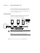


WIRING THE MODBUS CARD
EATON Powerware
®
Modbus
®
Card User’s Guide S 164201376 Rev C www.powerware.com
9
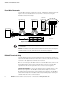
For four-wire networks. All four RS-485 network signals including TxD(+),
RxD(+), TxD(–), and RxD(–) must be connected to the terminal strip as
illustrated in Table 1. Verify that the Modbus Card J9 and J10 jumpers
are set to the four-wire option (see “Four-Wire Communication” on
page 4).
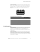
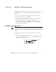
TxD+ RxD+ TxD– RxD– GND
12345
Figure 8. RS-485 Terminal Strip
Table 1. RS-485 Terminal Strip Pin Assignments
Pin Number Modbus Card Signal Name
RS-485 Network Signals
Master Signal Name
1 TxD(+) RxD(+)
2 RxD(+) TxD(+)
3 TxD(–) RxD(–)
4 RxD(–) TxD(–)
5 Signal common Signal common
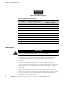
RS-485 Modbus Port
For two-wire networks. Connect the RS-485 network signal TxD(+) to the
Modbus RxD(+) input signal (DB -9 Pin 1). Connect the RS-485 network
signal TxD(–) to the Modbus RxD(–) input signal (DB-9 Pin 6). The
Modbus Card factory-default jumper setting for J9 and J10 is two-wire
communication.
For four-wire networks. All four RS-485 network signals including TxD(+),
RxD(+), TxD(–), and RxD(–) must be connected to the pin assignments
on the DB-9 connector as illustrated in Table 2. Verify that the Modbus
Card J9 and J10 jumpers are set to the four-wire option (see “Four-Wire
Communication” on page 4).