02/15/01 ® Powerware 5119 User’s Guide 1000-3000 VA www.powerware.
Requesting a Declaration of Conformity The EC Declaration of Conformity is available upon request for products with a CE mark. For copies of the EC Declaration of Conformity, contact: Powerware Corporation Koskelontie 13 FIN-02920 Espoo Finland Phone: +358-9-452661 Fax: +358-9-452-66395 EMC Statement Some configurations are classified under EN50091-2 as “Class-A UPS for Unrestricted Sales Distribution.” For these configurations, the following applies: WARNING This is a Class A-UPS Product.
Class A Statement for FCC and ICES (2000 VA - 3000 VA) For Users in the United States Only NOTE This equipment has been tested and found to comply with the limits for a Class A digital device pursuant to Part 15 of FCC Rules. These limits are designed to provide reasonable protection against harmful interference when this equipment is operated in a commercial environment.
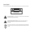
Special Symbols The following are examples of symbols used on the UPS to alert you to important information: CAUTION Risk of Electric Shock Do Not Open Cover CAUTION To reduce the risk of electric shock, Do not remove cover (or back) No user-serviceable parts inside Refer servicing to the factory RISK OF ELECTRIC SHOCK - Indicates that a risk of electric shock is present and the associated warning should be observed.
TABLE OF CONTENTS 1 Powerware 5119 – One of the Best! . . . . . . . . . . . . . . . . . . . . . . . . . . . . . . . . . . 1 2 Installation . . . . . . . . . . . . . . . . . . . . . . . . . . . . . . . . . . . . . . . . . . . . . . . . . . . . . 3 Inspecting the Equipment . . . . . . . . . . . . . . . . . . . . . . . . . . . . . . . . . . . . . . . . . . . . . . . . . . . . . . . Safety Precautions . . . . . . . . . . . . . . . . . . . . . . . . . . . . . . . . . . . . . . . . . . . . . . . . . . . . . . . .
Table of Contents 6 Additional UPS Features . . . . . . . . . . . . . . . . . . . . . . . . . . . . . . . . . . . . . . . . . . 25 Communication Port Configurations . . . . . . . . . . . . . . . . . . . . . . . . . . . . . . . . . . . . . . . . . . . . . . . . Communication Indicator . . . . . . . . . . . . . . . . . . . . . . . . . . . . . . . . . . . . . . . . . . . . . . . . . . . . . Pin Out . . . . . . . . . . . . . . . . . . . . . . . . . . . . . . . . . . . . . . . . . . . . . . . . . . . . . . . .
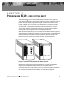
CHAPTER 1 POWERWARE 5119 – ONE OF THE BEST! The Powerware9 5119 uninterruptible power system (UPS) protects your sensitive electronic equipment from basic power problems such as power failures, power sags, power surges, brownouts, and line noise. Power outages can occur when you least expect it and power quality can be erratic. These power problems have the potential to corrupt critical data, destroy unsaved work sessions, and damage hardware — causing hours of lost productivity and expensive repairs.
Powerware 5119 – One of the Best! Providing outstanding performance and reliability, the Powerware 5119’s unique benefits include the following: 2 : Advanced Battery Management (ABMZ) doubles battery service life, optimizes recharge time, and provides a warning up to 60 days before the end of useful battery life. : Buck and Double Boost regulation ensures consistent voltage to your load by correcting voltage fluctuations without using battery power.
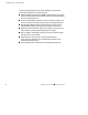
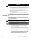
CHAPTER 2 INSTALLATION This section explains: : Equipment inspection : Safety precautions : UPS installation : UPS rear panels Inspecting the Equipment If any equipment has been damaged during shipment, keep the shipping cartons and packing materials for the carrier or place of purchase and file a claim for shipping damage. If you discover damage after acceptance, file a claim for concealed damage.
Installation WARNING : This UPS contains its own energy source (batteries). The output receptacles may carry live voltage even when the UPS is not connected to an AC supply. : Do not remove or unplug the input cord when the UPS is turned on. This removes the safety ground from the UPS and the equipment connected to the UPS. : To reduce the risk of fire or electric shock, install this UPS in a temperature and humidity controlled, indoor environment, free of conductive contaminants.
Installation 3. On 230V models, plug the UPS power cord into the input connector on the UPS rear panel. Customer-supplied power cords must correctly rated for the UPS (see “Specifications” on page 29). You can also use the power cord from the largest load if it is correctly rated. 4. Plug the UPS power cord into a wall outlet or power source. The UPS conducts a self-test and enters Standby mode. If a red Site Wiring Fault or Battery Service indicator stays on, see Table 11 on page 33.
Installation 2 5 Connect communication cable from computer to UPS (optional) Battery Cabinet Connect equipment to UPS UPS 1 Connect battery to UPS (if applicable) 3 6 & 4 Powerware® 5119 User’s Guide : www.powerware.
Installation UPS Rear Panels This section shows the rear panels of all Powerware 5119 models. Powerware® 5119 User’s Guide : www.powerware.
Installation 8 Powerware® 5119 User’s Guide : www.powerware.
Installation Communication Port 10A, IEC-320 Input Connector Battery Connector Input Circuit Breaker Load Segment 1 (Three IEC-320 Receptacles) Load Segment 2 (Three IEC-320 Receptacles) / 2 $ ' Option Slot Load Segment 3 (Three IEC-320 Receptacles) Network Transient Protector Figure 8.
Installation 10 Powerware® 5119 User’s Guide : www.powerware.
CHAPTER 3 OPERATION This section describes: : Turning the UPS on and off : Starting the UPS on battery : Standby mode : The UPS front panel and LEDs : Initiating the self-test Turning the UPS On After the UPS is connected to a power source, it conducts a self-test and enters Standby mode. To turn on the UPS, press the On button on the front panel (shown in Figure 10). The Power On indicator illuminates indicating that power is available from the rear receptacles.
Operation UPS Front Panel The UPS front panel LEDs indicate how the UPS is operating and also alert you of potential power problems. Figure 10 shows the UPS front panel indicators and controls. Battery Charge LEDs AC Input LEDs Site Wiring Fault Indicator Load Level LEDs Communication Indicator On Button Off Button Test/Alarm Reset Button 12 Powerware® 5119 User’s Guide : www.powerware.
Operation AC Input LEDs The AC Input LEDs show information about the utility power coming into the UPS (see Figure 11). Normal Utility Input (Buck and Single Boost) Double Boost is on Figure 11. AC Input LEDs (Normal Mode) The second LED indicates that the UPS is operating normally from utility power. The UPS is providing consistent voltage with the Buck and Single Boost feature. The third LED indicates that the UPS is using the Double Boost feature to automatically correct voltage fluctuations.
Operation Load Level LEDs The front panel displays the total load current or watts plugged into the UPS (see Figure 13). 66-100% 33-66% 5-33% Figure 13. Load Level LEDs (Normal Mode) Each LED represents 1/3 of a full load rating. When the UPS is approximately fully loaded (66-100%), all three LEDs illuminate. If the load is 33-66% of UPS capacity, the third and fourth LED illuminate. The last LED illuminates if the load is between 5% and 33%.
CHAPTER 4 CONFIGURATION This section explains: : Why you may want to change factory defaults : How to reconfigure options Why Change Factory Defaults? Nominal Input Voltage When the utility power consistently fluctuates, the UPS repeatedly corrects the input voltage by switching to battery power when the nominal input range is: : Higher than +20% of 120V or 230V nominal : Lower than -30% of 120V or 230V nominal : Higher than +20% and lower than -30% of 120V or 230V nominal You can configure the
Configuration CAUTION DO NOT press the Off button while the UPS is in Configuration mode; pressing button removes all power to your equipment. the Off 1. Press and hold the On button and the button simultaneously for one beep. The UPS switches to Configuration mode. 2. Press the On button to scroll through the options. Each time you press the button, the UPS beeps. The LED for the selected option blinks (see Figure 14 and Table 1).
Configuration Table 1. Configuration Mode LEDs and Options LED Option Power On Indicator Explanation 120/230V Nominal Input Voltage ON (default) Nominal input voltage on low voltage models is 120V and on high voltage models is 230V; all other nominal input voltages are disabled. OFF* 120/230V is disabled; one of the other input voltage options is selected. *This is the default for models that are factory-configured for 100V or 208V (see the rating on the UPS rear panel).
Configuration LED Option Power On Indicator Explanation Shutdown Delay ON (default) 5-second delay before unconditional shutdown after the UPS receives a signal from a computer via the communication port. OFF 180-second delay before unconditional shutdown after the UPS receives a signal from a computer via the communication port. When this LED is not enabled, the user can also create a new delay time by reconfiguring the communication port.
CHAPTER 5 UPS MAINTENANCE This section explains how to: : Care for the UPS and batteries : Replace the batteries : Test new batteries : Recycle used batteries UPS and Battery Care For the best preventive maintenance, keep the area around the UPS clean and dust-free. If the atmosphere is very dusty, clean the outside of the system with a vacuum cleaner. For full battery life, keep the UPS at an ambient temperature of 25°C (77°F).
UPS Maintenance Replacing Batteries The hot-swappable battery feature allows you to replace the UPS batteries easily without turning the UPS off or disconnecting the load. If you prefer to remove input power to change the battery: 1) Press the Off button and then unplug the UPS; 2) Wait 60 seconds while the internal processor shuts down before you disconnect the battery. Consider all warnings, cautions, and notes before replacing batteries.
UPS Maintenance How to Replace External Batteries Use the following steps to replace external batteries: 1. Unplug the battery cable from the UPS and remove the old battery. See “Recycling the Batteries” on page 24 for proper disposal. 2. Plug the new battery cabinet into the UPS as shown in Figure 15. UPS Battery Cabinet Battery Connector Plug the battery cable into the battery connector Figure 15. External Battery Connections (120V Model Shown) Powerware® 5119 User’s Guide : www.powerware.
UPS Maintenance How to Replace Internal Batteries Use the following steps to replace internal batteries: 1. Pull the front panel forward and snap into place as shown. 22 Powerware® 5119 User’s Guide : www.powerware.
UPS Maintenance 4. Remove the old battery. See “Recycling the Batteries” on page 24 for proper disposal. 5. Connect the new batteries to the UPS as shown in Figure 16 and reinstall. Red Cable from UPS Positive Terminal Black Cable from UPS Negative Terminal 1000 VA Models Red Connector from UPS Black Cable from UPS Red Battery Connector 1500 VA Models Negative Terminal (Black) Figure 16.
UPS Maintenance Recycling the Used Battery Contact your local recycling or hazardous waste center for information on proper disposal of the used battery. WARNING : Do not dispose of battery or batteries in a fire. Batteries may explode. Proper disposal of batteries is required. Refer to your local codes for disposal requirements. : Do not open or mutilate the battery or batteries. Released electrolyte is harmful to the skin and eyes. It may be toxic.
CHAPTER 6 ADDITIONAL UPS FEATURES This section describes: : UPS communication capabilities : The Network Transient Protector : Load segments : Option modules Communication Port Configurations To establish communication between the UPS and a computer, connect your computer to the UPS communication port using the supplied communication cable.
Additional UPS Features Pin Out As shown in Table 2, Pins 1 and 2 operate in two modes: Basic Alarms mode and Serial Data mode. Basic Alarms mode has AC fail alarm and output shutdown. Serial Data mode is UPS Code II compliant. The system always starts in Basic Alarms mode. When serial data is received at Pin 1, the function of Pin 1 and Pin 2 changes to Serial Data mode. If serial data has not been received before going to battery power, serial communication is disabled until AC input power returns.
Additional UPS Features Network Transient Protector The Network Transient Protector, shown in Figure 18, is located on the rear panel and has jacks labeled IN and OUT. This feature accommodates a single RJ-45 (10BaseT) network connector. Low voltage models can also accommodate an RJ-11 telephone connector that provides protection for modems, fax machines, or other telecommunications equipment.
Additional UPS Features 28 Powerware® 5119 User’s Guide : www.powerware.
CHAPTER 7 SPECIFICATIONS This section provides the following specifications for the Powerware 5119 models: : Electrical input and output : Weights and dimensions : Environmental and safety : Indicators and controls : Battery Table 3.
Specifications Table 5.
Specifications Table 7. Environmental and Safety 120V Models Operating Temperature 230V Models 0°C to 40°C (32°F to 104°F); UL tested 25°C (77°F) Storage Temperature -20°C to 60°C (-4°F to 140°F) Relative Humidity 5-95% noncondensing Operating Altitude Up to 3,000 meters above sea level Audible Noise Less than 45 dBA typical Surge Suppression Safety Conformance IEEE 587/ANSI C62.41 Category B UL 1778; CAN/CSA C22.2, No. 107.1 UL 1778; CAN/CSA C22.2, No. 107.
Specifications Table 10. Battery Run Times (in Minutes) Load (VA) 1000 Model 1500 Model 2000 Model 2400 Model 3000 Model 300 49 79 92 162 162 500 21 38 55 97 97 700 14 17 34 62 62 1000 8 6 24 43 43 8 13 23 23 8 16 16 13 13 1500 2000 2400 3000 7 NOTE Battery times are approximate and vary depending on the load configuration and battery charge. 32 Powerware® 5119 User’s Guide : www.powerware.
CHAPTER 8 TROUBLESHOOTING This section explains: : UPS alarms and conditions : How to silence an alarm : Service and support Audible Alarms and UPS Conditions The UPS has an audible alarm feature to alert you of potential power problems. Use Table 11 to determine and resolve the UPS alarms and conditions. Silencing an Audible Alarm To silence the alarm for an existing fault, press the button. If UPS status changes, the alarm beeps, overriding the previous alarm silencing. Table 11.
Troubleshooting Alarm or Condition Possible Cause Action The Low Battery Alarm does not give enough warning. The batteries need charging or service. Plug the UPS into a wall outlet for 24 hours to charge the battery. After charging the battery, press and hold the button for 3 seconds; then check the Battery Service indicator. If the Battery Service indicator is still on, see “UPS Maintenance” on page 19 to replace the battery. The Low Battery Alarm is not set appropriately. Change the alarm setting.
Troubleshooting Alarm or Condition Battery Service Possible Cause Action The battery may be fully discharged because of a long storage period or failing because of age. Plug the UPS into a wall outlet for 24 hours to charge the battery. After charging the battery, press and hold the button for 3 seconds; then check the Battery Service indicator. If the Battery Service indicator is still on, see “UPS Maintenance” on page 19 to replace the battery. The battery is not connected correctly.
Troubleshooting If repair is required, you will be given a Returned Material Authorization (RMA) Number. This number must appear on the outside of the package and on the Bill Of Lading (if applicable). Use the original packaging or request packaging from the Help Desk or distributor. Units damaged in shipment as a result of improper packaging are not covered under warranty. A replacement or repair unit will be shipped, freight prepaid for all warrantied units.