Powerware® 9155 Parallel UPS 8–15 kVA User’s Guide
Class A EMC Statements FCC Part 15 NOTE This equipment has been tested and found to comply with the limits for a Class A digital device, pursuant to part 15 of the FCC Rules. These limits are designed to provide reasonable protection against harmful interference when the equipment is operated in a commercial environment.
Requesting a Declaration of Conformity Units that are labeled with a CE mark comply with the following harmonized standards and EU directives: S Harmonized Standards: IEC 62040-1-1 and IEC 62040-2; IEC 60950 Third Edition S EU Directives: 73/23/EEC, Council Directive on equipment designed for use within certain voltage limits 93/68/EEC, Amending Directive 73/23/EEC 89/336/EEC, Council Directive relating to electromagnetic compatibility 92/31/EEC, Amending Directive 89/336/EEC relating to EMC The EC Dec
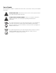
Special Symbols The following are examples of symbols used on the UPS or accessories to alert you to important information: RISK OF ELECTRIC SHOCK - Indicates that a risk of electric shock is present and the associated warning should be observed. CAUTION: REFER TO OPERATOR’S MANUAL - Refer to your operator’s manual for additional information, such as important operating and maintenance instructions. This symbol indicates that you should not discard the UPS or the UPS batteries in the trash.
Table of Contents 1 Introduction . . . . . . . . . . . . . . . . . . . . . . . . . . . . . . . . . . . . . . . . . . . . . . . . . . . . . . . . . 1 2 Safety Warnings . . . . . . . . . . . . . . . . . . . . . . . . . . . . . . . . . . . . . . . . . . . . . . . . . . . . . 3 3 UPS Setup . . . . . . . . . . . . . . . . . . . . . . . . . . . . . . . . . . . . . . . . . . . . . . . . . . . . . . . . . . 7 Inspecting the Equipment . . . . . . . . . . . . . . . . . . . . . . . . . . . . . . . . . . . .
TABLE OF CONTENTS ii EATON Powerware® 9155 Parallel UPS (8–15 kVA) User’s Guide S 164201592 Rev C www.powerware.
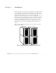
Chapter 1 Introduction A parallel system with up to three uninterruptible power supplies (UPSs) can be installed to provide a parallel capacity and/or redundant system. This load sharing system provides more capacity than a single UPS and can provide backup, depending on the load and configuration. In addition, when one UPS is taken out of service for maintenance or is not operating properly, a redundant UPS continues to supply uninterrupted power to the critical load.
INTRODUCTION 2 EATON Powerware® 9155 Parallel UPS (8–15 kVA) User’s Guide S 164201592 Rev C www.powerware.
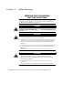
Chapter 2 Safety Warnings IMPORTANT SAFETY INSTRUCTIONS SAVE THESE INSTRUCTIONS This manual contains important instructions that you should follow during installation and maintenance of the UPS and batteries. Please read all instructions before operating the equipment and save this manual for future reference. DANGER This UPS contains LETHAL VOLTAGES. All repairs and service should be performed by AUTHORIZED SERVICE PERSONNEL ONLY. There are NO USER SERVICEABLE PARTS inside the UPS.
SAFETY WARNINGS Consignes de Sécurité CONSIGNES DE SÉCURITÉ IMPORTANTES CONSERVER CES INSTRUCTIONS CE MANUEL CONTIENT DES CONSIGNES DE SÉCURITÉ IMPORTANTES DANGER! Cet onduleur contient des TENSIONS MORTELLES. Toute opération d’entretien et de réparation doit être EXCLUSIVEMENT CONFIÉE A UN PERSONNEL QUALIFIÉ AGRÉÉ. AUCUNE PIÈCE RÉPARABLE PAR L’UTILISATEUR ne se trouve dans l’onduleur. WARNING S Cet onduleur renferme sa propre source d’énergie (batteries).
SAFETY WARNINGS Advertencias de Seguridad INSTRUCCIONES DE SEGURIDAD IMPORTANTES GUARDE ESTAS INSTRUCCIONES ESTE MANUAL CONTIENE INSTRUCCIONES DE SEGURIDAD IMPORTANTES PELIGRO Este SIE contiene VOLTAJES MORTALES. Todas las reparaciones y el servicio técnico deben ser efectuados SOLAMENTE POR PERSONAL DE SERVICIO TÉCNICO AUTORIZADO. No hay NINGUNA PARTE QUE EL USUARIO PUEDA REPARAR dentro del SIE. WARNING S Este SIE contiene su propia fuente de energía (las baterías).
SAFETY WARNINGS 6 EATON Powerware® 9155 Parallel UPS (8–15 kVA) User’s Guide S 164201592 Rev C www.powerware.
Chapter 3 UPS Setup This chapter describes: S Equipment inspection S Floor loading and clearances S Unloading the cabinet(s) The instructions are intended for the chief operator/system supervisor, electrical consultants, and installation electricians. Local regulations and electrical code must be followed during the UPS installation.
UPS SETUP Floor Loading When planning the installation, consider the UPS weight for floor loading. The strength of the installation surface must be adequate for point and distributed loadings. The approximate weights are shown in the following table.
UPS SETUP Unloading the Cabinet(s) The following tools are required for unloading the cabinet(s): S 15 mm wrench or socket S 7 mm nutdriver or socket CAUTION The UPS and Extended Battery Module (EBM) are heavy (see page 8). Unloading the cabinets requires at least two people to safely remove the cabinets from the pallet. To remove the UPS or EBM from the shipping pallet: 1. Remove the two M10 bolts securing the stabilizing bracket to the pallet (see Figure 2). M10 Bolts Figure 2.
UPS SETUP 3. Remove the front cover from the bottom cabinet to access the front shipping bracket. Press and release the handle latch at the bottom of the cover and then lift the cover up and off the cabinet. 4. Remove the three M10 bolts securing the rear shipping pad to the pallet and remove the shipping pad (see Figure 3). NOTE Hold the back of the cabinet so that the bolts can be removed easily without the cabinet rolling backward. 5.
UPS SETUP NOTE Be sure to support the front and back of the cabinet when rolling it off the pallet to prevent tipping. 7. Slowly roll the cabinet toward the rear of the pallet. Once the pallet tilts, continue rolling the cabinet down the pallet until the cabinet touches the floor (see Figure 4). If needed, adjust the leveling feet so that the cabinet will roll. Figure 4. Unloading the Cabinet 8. With the cabinet supported, slowly pull the pallet away from the cabinet (see Figure 5). Figure 5.
UPS SETUP 12 EATON Powerware® 9155 Parallel UPS (8–15 kVA) User’s Guide S 164201592 Rev C www.powerware.
Chapter 4 Parallel Installation The Powerware 9155 has the following power connections: S 2-phase (L1 and L2), neutral, and ground connection for rectifier/bypass input S 2-phase (L1 and L2), neutral, and ground connection for load output The nominal input/output voltages are: S 100/200, 110/220, or 120/240 Vac with 180° phase displacement S 120/208 or 127/220 Vac with 120° phase displacement Output overcurrent protection and disconnect switch must be provided by others.
PARALLEL INSTALLATION WARNING Only qualified service personnel (such as a licensed electrician) should perform the UPS installation and initial startup. Risk of electrical shock. To hardwire the parallel system: 1. Verify that the electrical connections to the installation site have been properly installed. 2. A wall-mounted, user-supplied, readily-accessible disconnection device must be incorporated in the input wiring.
PARALLEL INSTALLATION 5. Remove the parallel tie cabinet front cover (see Figure 6). Parallel Cabinet Figure 6. Parallel Tie Cabinet Front Cover 6. Remove the internal cover to gain access to the breakers (see Figure 7). Internal Cover Figure 7. Internal Cover EATON Powerware® 9155 Parallel UPS (8–15 kVA) User’s Guide S 164201592 Rev C www.powerware.
PARALLEL INSTALLATION 7. Punch holes for the conduit (AC input, each UPS output, and load connection) using a Greenlee® punch or similar device. 8. Verify that the parallel bypass breaker is in the OFF position (see Figure 8). 9. Mount the parallel tie cabinet to the wall and install the conduit. Figure 8. Parallel Bypass Breaker 16 EATON Powerware® 9155 Parallel UPS (8–15 kVA) User’s Guide S 164201592 Rev C www.powerware.
PARALLEL INSTALLATION 10. Verify that each UPS battery circuit breaker is in the OFF position (see Figure 9). Battery Connector ON OFF UPS Wiring Access Cover Battery Circuit Breaker Conduit Landing Figure 9. UPS Rear View (2-High Shown) 11. From each UPS, remove the UPS wiring access cover and retain (see Figure 9). 12. Hardwire the UPS input terminations (TB1-1 through TB1-5) for each UPS. See Table 2 for specifications and Figure 10 for a detailed view of the UPS terminal block.
PARALLEL INSTALLATION NOTE Input neutral must be wired for proper operation. Failure to connect an input neutral will void the warranty. Table 2. UPS Terminal Block Wiring Wire Function Input p Output p Terminal Position Upstream Circuit Breaker Minimum Wire Size* Ground TB1-1 L1 TB1-3 Neutral TB1-4 L2 TB1-5 L1 TB1-6 3 AWG Neutral TB1-7 3 AWG L2 TB1-8 3 AWG Ground TB1-9 8 AWG Tightening Torque Conduit Connection (Entry Size) 25 lb in (2.
PARALLEL INSTALLATION 13. Hardwire the output terminations (TB1-6 through TB1-9) from each UPS to the parallel tie cabinet (see Figure 11). Ground Neutral UPS 1 Line 1 Line 2 UPS 3 Line 1 Line 2 Line 1 Line 2 UPS 2 Figure 11. UPS Output to Parallel Tie Cabinet Wiring 14. Replace each UPS wiring access cover. EATON Powerware® 9155 Parallel UPS (8–15 kVA) User’s Guide S 164201592 Rev C www.powerware.
PARALLEL INSTALLATION 15. Hardwire the load to the parallel tie cabinet (see Figure 12). Line 1 Line 2 Neutral Figure 12. Load Connections 20 EATON Powerware® 9155 Parallel UPS (8–15 kVA) User’s Guide S 164201592 Rev C www.powerware.
PARALLEL INSTALLATION 16. Wire the AC input to the bypass breaker (see Figure 13). Neutral Line 1 Line 2 Figure 13. Parallel AC Input Wiring 17. Verify the phase rotation for each UPS and the bypass input. 18. Reinstall the internal cover removed in Step 6. 19. Reinstall the parallel tie cabinet front cover removed in Step 5. 20. Continue to “Installing Options” on page 23. EATON Powerware® 9155 Parallel UPS (8–15 kVA) User’s Guide S 164201592 Rev C www.powerware.
PARALLEL INSTALLATION Figure 14. Parallel Wiring Diagram 22 EATON Powerware® 9155 Parallel UPS (8–15 kVA) User’s Guide S 164201592 Rev C www.powerware.
Chapter 5 Installing Options This section describes the Powerware Hot Sync CAN Bridge Card. For other options, such as additional X-Slott cards, Powerware LanSafet Power Management Software, remote emergency power-off (REPO), relay output contacts, or programmable signal inputs, refer to the Powerware 9155 UPS (8–15 kVA) User’s Guide. Figure 15 shows the location of the communication options and control terminals on the UPS.
INSTALLING OPTIONS Powerware Hot Sync CAN Bridge Card The Powerware Hot Sync CAN Bridge Card, shown in Figure 16, can be installed to provide connectivity for operational mode control and metering of a parallel system at any UPS in the system. Plug-in Terminal Block Figure 16. Powerware Hot Sync CAN Bridge Card To install the Powerware Hot Sync CAN Bridge Card: 1. Remove the front covers of all cabinets, starting with the top cabinet.
INSTALLING OPTIONS 2. If you ordered a factory-configured parallel UPS, remove the Powerware Hot Sync CAN Bridge Card from the X-Slot on the front of the UPS. Retain the screws. Otherwise, remove the X-Slot communication bay cover and retain the screws. 3. Set the jumper pins on the Powerware Hot Sync CAN Bridge Card according to the parallel configuration (see Figure 18): S If only two UPSs are paralleled, then set both cards to Pins 1 and 2.
INSTALLING OPTIONS NOTE If you are installing another X-Slot card, be sure to install the Powerware Hot Sync CAN Bridge Card in X-Slot 2. 4. Loosely install the Powerware Hot Sync CAN Bridge Card into an open X-Slot on the front of the UPS. You may want to remove the terminal block from the CAN Bridge Card for better wiring access. 5. Strip shielded, four-wire, twisted-pair wire for CAN Bridge Card wiring. Recommended wire size is 18 AWG maximum. 6.
INSTALLING OPTIONS UPS #1 UPS #2 UPS #3 Figure 19. CAN Bridge Card Wiring EATON Powerware® 9155 Parallel UPS (8–15 kVA) User’s Guide S 164201592 Rev C www.powerware.
INSTALLING OPTIONS 8. Secure the Powerware Hot Sync CAN Bridge Card with the screws removed in Step 2. 9. On the bottom cover (and also the middle cover if 3-high), remove a knockout tab in the top edge of the cover for each cable: With wire cutters, cut either side of the tab and twist down to remove the tab (see Figure 20). Figure 20. Removing Knockout Tabs 10. Route the cable(s) to the approximate location of the cover access holes.
INSTALLING OPTIONS 11. Reinstall the front covers, starting with the bottom cabinet (see Figure 21). Hang the top edge of the cover on the cabinet first, then lower the bottom edge and snap into place. Be sure the cables fit in the access holes in the covers. Figure 21. Reinstalling the Front Covers 12. Continue to “Stabilizing the Cabinet” on page 31 to complete the parallel UPS installation. EATON Powerware® 9155 Parallel UPS (8–15 kVA) User’s Guide S 164201592 Rev C www.powerware.
INSTALLING OPTIONS 30 EATON Powerware® 9155 Parallel UPS (8–15 kVA) User’s Guide S 164201592 Rev C www.powerware.
Chapter 6 Stabilizing the Cabinet NOTE For seismic installations, you MUST order and install a Powerware 9155 UPS seismic kit; do not use the following instructions. NOTE For non-seismic installations, you MUST install the stabilizing bracket on all 3-high cabinets. The stabilizing bracket is optional for 2-high cabinets. To stabilize the cabinet(s): 1. Lower the leveling feet to prevent the cabinet from rolling. Figure 22. Lowering the Leveling Feet 2.
STABILIZING THE CABINET 4. Continue to one of the following sections: S “Extended Battery Module Installation” on page 35 to install optional EBMs. S “Operation” on page 39 to start up the parallel UPS system. M4 Screws Figure 23. Stabilizing Bracket with One Cabinet 32 EATON Powerware® 9155 Parallel UPS (8–15 kVA) User’s Guide S 164201592 Rev C www.powerware.
STABILIZING THE CABINET M4 Screws Figure 24. Stabilizing Bracket with Two Cabinets M4 Screws Figure 25. Stabilizing Bracket with Three Cabinets EATON Powerware® 9155 Parallel UPS (8–15 kVA) User’s Guide S 164201592 Rev C www.powerware.
STABILIZING THE CABINET 34 EATON Powerware® 9155 Parallel UPS (8–15 kVA) User’s Guide S 164201592 Rev C www.powerware.
Chapter 7 Extended Battery Module Installation NOTE A maximum of 22 battery strings can be installed in one configuration, including UPS batteries (4 EBM-64 models or 3 EBM-96 models). UPS-32 models contain 2 strings; UPS-64 models contain 4 strings; EBM-64 models contain 4 strings; and EBM-96 models contain 6 strings. NOTE For non-seismic installations, you MUST install the stabilizing bracket on all 3-high cabinets. The stabilizing bracket is optional for 2-high cabinets.
EXTENDED BATTERY MODULE INSTALLATION EBM Battery Circuit Breaker EBM Battery Connector Rear Ground Strap UPS Battery Connector ON OFF UPS Battery Circuit Breaker EBM Cable Figure 26. Typical EBM Installation (2-High Cabinets Shown) 36 EATON Powerware® 9155 Parallel UPS (8–15 kVA) User’s Guide S 164201592 Rev C www.powerware.
EXTENDED BATTERY MODULE INSTALLATION 8. Remove the top front covers of all cabinets. Press and release the handle latch at the bottom of the cover and then lift the cover up and off the cabinet. 9. Install the remaining ground straps between each cabinet (see Figure 27). 10. Reinstall the top front covers removed in Step 8. Hang the top edge of the cover on the cabinet first, then lower the bottom edge and snap into place. 11. Continue to “Operation” on page 39 to start up the UPS.
EXTENDED BATTERY MODULE INSTALLATION 38 EATON Powerware® 9155 Parallel UPS (8–15 kVA) User’s Guide S 164201592 Rev C www.powerware.
Chapter 8 Operation This chapter contains information on how to use the Powerware 9155, including front panel operation, UPS startup and shutdown, and configuring the UPS for Extended Battery Modules (EBMs). Control Panel Functions The UPS has a four-button graphical LCD with backlight. It provides useful information about the UPS itself, load status, events, measurements, and settings (see Figure 28).
OPERATION The following table shows the indicator status and description. Indicator Green Status Description On The UPS is operating normally. Flashing S The UPS is starting up or is shut down and waiting for power to return. S A new information message is active. S Bypass is not available. Off The UPS is turned off and will not turn on automatically. On The UPS is in Battery mode. On The UPS is in Bypass mode. On The UPS has an active alarm. Flashing There is a new UPS alarm condition.
OPERATION The following table shows the basic menu structure. Table 3.
OPERATION User Settings The following table displays the options that can be changed by the user. NOTE Changes to the output voltage or frequency options should be made before turning on the UPS; otherwise, the changes do not take effect. Table 4.
OPERATION Table 4. User Settings (continued) Description Available Settings Default Setting Modem Config Modem Installation Set Modem Call Events Event #0 Call modem: no Set Modem Init String ATZ0 Set Modem Call Command None Set Modem Communication Password None Start Screen Eaton Powerware logo Mimic screen Eaton Powerware logo User Password Enabled/Disabled If Enabled is selected, the password is USER.
OPERATION Table 4. User Settings (continued) Description Available Settings Default Setting Synchronization Window ±0.5 through ±3.0 Hz (0.1 Hz increments) ±2.0 Hz Unsynchronized Transfer to Bypass Allowed/Not Allowed Not Allowed Output Frequency Slew Rate 0.1 though 5 hertz per second (0.1 Hz increments) 0.
OPERATION Parallel UPS Startup WARNING Only qualified service personnel (such as a licensed electrician) should perform the UPS installation and initial startup. Risk of electrical shock. Verify that UPS installation has been carried out correctly and the UPS ground has been connected. NOTE In a parallel capacity system (2+0 or 2+1), determine the minimum number of UPSs required for capacity. To start up the parallel system: 1.
OPERATION 6. Configure the UPS for parallel operation through the front panel: S Press any button on the front panel display to activate the menu options. S Using the button, scroll to the Settings menu, and then press the button twice to select the User Settings menu. S Using the button, scroll to the Parallel Operation Settings option and press the S Press the button. button to select the Parallel Unit Number option.
OPERATION 9. Shut down each UPS: S Press the button on the front panel display and then press the button to select the TURN UPS ON/OFF menu. S Press the button to select the UPS Off option; press the button. S Confirm the selection. Press and hold the button for three seconds, until the UPS stops beeping. S Switch the UPS battery circuit breaker to the OFF position. The UPS is disconnected from the batteries and is on logic power only. 10.
OPERATION 17. Select the System On option; press the 18. Confirm the selection. Press and hold the seconds, until the UPS stops beeping. button. button for three The UPS goes to Bypass mode for five seconds, and then the indicator illuminates. Each UPS should be in Normal mode. 19. Press the ESC button until the Eaton Powerware logo appears. 20.
OPERATION Configuring the UPS for EBMs NOTE Each UPS in a parallel system must have its own EBM and the same number of EBMs to ensure consistent runtimes. To ensure maximum battery runtime, configure the UPS for the correct number of EBMs: 1. Press any button on the front panel display to activate the menu options. 2. Using the 3. Press the 4. Using the button, scroll to the Number of Battery Strings option button. and press the 5.
OPERATION Parallel System Shutdown To remove power to the parallel UPS system output: 1. Press any button on the front panel display to activate the menu options. 2. Press the button on the front panel display and then press the button to select the TURN UPS ON/OFF menu. 3. Press the button to select the System Off option; press the button. 4. Confirm the selection. Press and hold the seconds, until the UPS stops beeping. button for three The UPS removes power to the parallel UPS system output.
OPERATION Individual UPS Shutdown To shut down a single UPS in the parallel system: 1. Press any button on the front panel display to activate the menu options. 2. Press the button on the front panel display and then press the button to select the TURN UPS ON/OFF menu. 3. Press the button to select the UPS Off option; press the button. 4. Confirm the selection. Press and hold the seconds, until the UPS stops beeping. button for three The input contactor opens. 5.
OPERATION Restarting the Parallel System To restart the parallel system: 1. Verify that all UPS breakers on the parallel tie cabinet are in the OFF position. 2. Switch on utility power where the UPSs are connected. 3. Wait for the front panel LCD to illuminate. The 4. indicator flashes on each UPS. Switch all battery circuit breakers to the ON position. The indicator stops flashing on each UPS. 5. Switch the UPS breakers on the parallel tie cabinet to the ON position. 6.
Chapter 9 Parallel Bypass To switch the parallel UPS to maintenance bypass from Normal mode: 1. From any UPS, set the system to internal Bypass mode: S Using the button on the front panel display, scroll to the Control menu option and press the S Press the button. button to select the Go to Bypass Mode option. The and indicators illuminate, indicating the UPS system is operating in Bypass mode. 2. Switch the bypass breaker on the parallel tie cabinet to the ON position. 3.
PARALLEL BYPASS To return to Normal mode from maintenance bypass: 1. Verify that all UPS breakers on the parallel tie cabinet are in the OFF position. 2. Switch on utility power where the UPSs are connected. In a parallel capacity system (2+0 or 2+1), apply utility to the minimum number of UPSs required for capacity. NOTE Use the same UPS that was used to set internal bypass to return the parallel system to Normal mode. 3.
Chapter 10 Troubleshooting The Powerware 9155 is designed for durable, automatic operation and also alerts you whenever potential operating problems may occur. Usually the alarms shown by the control panel do not mean that the output power is affected. Instead, they are preventive alarms intended to alert the user. Use the following troubleshooting chart to determine the UPS alarm condition.
TROUBLESHOOTING Alarm or Condition Possible Cause Action Overtemperature UPS internal temperature is too high or the fan has failed. If you have an optional Maintenance Bypass Module or Power Distribution Module, turn the maintenance bypass switch to the SERVICE position. Otherwise, shut down the UPS. Clear vents and remove any heat sources. Allow the UPS to cool. Ensure the airflow around the UPS is not restricted.
TROUBLESHOOTING Alarm or Condition Possible Cause Action Check Parallel Board The UPS is not recognizing another parallel unit. From the UPS Status menu, select the Units on CAN Bus option and verify that all UPSs appear in the list. If any UPS is missing, verify the Powerware Hot Sync CAN Bridge Card connections and recheck the status from the UPS front panel. If all UPSs appear in the list, check the pull-chain wiring (see page 26). Set the system to internal Bypass mode (see page 53).
TROUBLESHOOTING Service and Support If you have any questions or problems with the UPS, call your Local Distributor or the Help Desk at one of the following telephone numbers and ask for a UPS technical representative.
*164201592C* 164201592 C