Powerware 9390 UPS Sidecar Installation and Operation Manual ® For use with 40–80 kVA and 100–160 kVA UPS Models
IMPORTANT SAFETY INSTRUCTIONS SAVE THESE INSTRUCTIONS This manual contains important instructions that you should follow during installation and maintenance of the UPS and batteries. Please read all instructions before operating the equipment and save this manual for future reference.
Table of Contents 1 Introduction . . . . . . . . . . . . . . . . . . . . . . . . . . . . . . . . . . . . . . . . . . . . . . . . . . . . . . . . . . . . . . . . . . . . . . . . . . . 1.1 1.2 1.3 1.4 1.5 1.6 Configurations . . . . . . . . . . . . . . . . . . . . . . . . . . . . . . . . . . . . . . . . . . . . . . . . . . . . . . . . . . . . . . . . . . . . . . . . . . . . . . . . . . . . . . . . Using This Manual . . . . . . . . . . . . . . . . . . . . . . . . . . . . . . . . . . . . . . . . . . . . . . .
TABLE OF CONTENTS 4.5 UPS Sidecar Operation – Maintenance Bypass Configuration . . . . . . . . . . . . . . . . . . . . . . . . . . . . . . . . . . . . . . . . . . . . . . . . . . . . . . . 4.5.1 Using the UPS when a UPS Sidecar is Installed . . . . . . . . . . . . . . . . . . . . . . . . . . . . . . . . . . . . . . . . . . . . . . . . . . . . . . . . . . . . 4.5.2 Transferring the UPS to Maintenance Bypass . . . . . . . . . . . . . . . . . . . . . . . . . . . . . . . . . . . . . . . . . . . . . . . . . .
List of Figures Figure 1-1. Powerware 9390 UPS (40–80 kVA) with UPS Sidecar . . . . . . . . . . . . . . . . . . . . . . . . . . . . . . . . . . . . . . . . . . . . . . . . . . Figure 1-2. Powerware 9390 UPS (100–160 kVA) with UPS Sidecar . . . . . . . . . . . . . . . . . . . . . . . . . . . . . . . . . . . . . . . . . . . . . . . . . Figure 2-1. 80 kVA UPS with UPS Sidecar . . . . . . . . . . . . . . . . . . . . . . . . . . . . . . . . . . . . . . . . . . . . . . . . . . . . . . . . . . . . . . . . . . .
LIST OF FIGURES This page intentionally left blank. iv EATON Powerware® 9390 UPS Sidecar Installation and Operation Manual S 164201586 Rev E www.powerware.
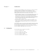
Chapter 1 Figure Introduction The Eaton® Powerware® 9390 UPS Sidecar is designed for use with the Powerware 9390 80 kVA 208/208V and 480/480V and 160 kVA 480/480V three-phase uninterruptible power systems (UPSs).
INTRODUCTION Figure 1-1. Powerware 9390 UPS (40–80 kVA) with UPS Sidecar 1-2 EATON Powerware® 9390 UPS Sidecar Installation and Operation Manual S 164201586 Rev E www.powerware.
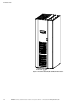
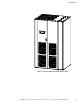
INTRODUCTION Figure 1-2. Powerware 9390 UPS (100–160 kVA) with UPS Sidecar EATON Powerware® 9390 UPS Sidecar Installation and Operation Manual S 164201586 Rev E www.powerware.
INTRODUCTION 1.2 Using This Manual This manual describes how to install and operate the Powerware 9390 UPS Sidecar. Read and understand the procedures described in this manual to ensure trouble-free installation and operation. The information in this manual is divided into the sections and chapters listed. At a minimum, Chapters 1, 2, and 4 should be examined. Read through each procedure before beginning the procedure.
INTRODUCTION 1.3 Conventions Used in This Manual This manual uses these type conventions: S Bold type highlights important concepts in discussions, key terms in procedures, and menu options. S Italic type highlights notes and new terms where they are defined. S Screen type represents information that appears on the screen or LCD. Icon Description Information notes call attention to important features or instructions.
INTRODUCTION 1.4 Safety Warnings IMPORTANT SAFETY INSTRUCTIONS SAVE THESE INSTRUCTIONS This manual contains important instructions that should be followed during installation and maintenance of the UPS Sidecar. Please read all instructions before operating the equipment and save this manual for future reference. The UPS Sidecar is designed for industrial or computer room applications, and contains safety shields behind the front panel.
INTRODUCTION 1.
INTRODUCTION This page intentionally left blank. 1-8 EATON Powerware® 9390 UPS Sidecar Installation and Operation Manual S 164201586 Rev E www.powerware.
Section I Installation EATON Powerware® 9390 UPS Sidecar Installation and Operation Manual S 164201586 Rev E www.powerware.
1-2 EATON Powerware® 9390 UPS Sidecar Installation and Operation Manual S 164201586 Rev E www.powerware.
Chapter 2 2.1 Installing the UPS Sidecar Figure Installation Plan and Unpacking Refer to the applicable Powerware 9390 installation and operation manual, listed in paragraph 1.5, for installation planning and unpacking. 2.2 Preliminary Installation Information WARNING Installation should be performed only by qualified personnel. Refer to the following while installing the UPS Sidecar: S Appendix A contains installation drawings and additional installation notes.
INSTALLING THE UPS SIDECAR 3. If not already removed, remove the screws securing the internal safety shield panel and remove the panel to gain access to the terminals. NOTE If a Bypass Input Breaker is not installed, a minimum of two separate feeds with upstream feeder breakers, or one feed with two upstream feeder breakers, must be provided: one for the UPS and one for the UPS Sidecar bypass input. DO NOT use one feed or a single-feeder breaker to supply both the UPS and Sidecar. 4.
INSTALLING THE UPS SIDECAR Front Panel UPS Cabinet UPS Sidecar Front Panel Attaching Screw Figure 2-1. 80 kVA UPS with UPS Sidecar EATON Powerware® 9390 UPS Sidecar Installation and Operation Manual S 164201586 Rev E www.powerware.
INSTALLING THE UPS SIDECAR 2.4 UPS Sidecar Installation – Parallel Redundant Configuration The method used to install the UPS Sidecar depends on the type of installation being undertaken. The UPS Sidecar can be installed as a line-up-and-match or standalone system. S To install a line-up-and-match parallel redundant system, continue to paragraph 2.4.1. S To install a standalone parallel redundant system, proceed to paragraph 2.4.3. 2.4.
INSTALLING THE UPS SIDECAR 1. Verify that the UPM 1 is properly installed and secured. Refer to the applicable Powerware 9390 installation and operation manual, listed in paragraph 1.5, for installation instructions. 2. On UPM 1, if not already removed, remove the screw securing the bottom of the UPS Sidecar front panel (see Figure 2-1 on page 2-3). Lift up the panel and remove. 3.
INSTALLING THE UPS SIDECAR 17. Align the holes in the other end of the bracket with the holes in the bottom right-hand side of the UPS Sidecar attached to UPM 1 (see Figure 2-3). Secure the bracket with M4 screws from the field kit. 18. Secure the large nut on the UPM 2 hinge. 19. Continue to paragraph 2.4.2.
INSTALLING THE UPS SIDECAR 2.4.2 Installing Line-up-and-Match Parallel Redundant Power Wiring NOTE Remove the UPS Sidecar top or bottom conduit landing plate to drill or punch conduit holes, or remove knockouts (see Drawing 164201546-5 starting on page A-27). NOTE Refer to the applicable Powerware 9390 installation and operation manual, listed in paragraph 1.5, for UPS cabinet wiring information and conduit and terminal locations.
INSTALLING THE UPS SIDECAR 2.4.3 Standalone Parallel Redundant Installation Use this procedure to install separately located UPMs (see Figure 2-4). UPM 1 has the Sidecar installed. The UPS Sidecar is a factory-installed integral part of the standard UPS cabinet. UPS Sidecar UPM 1 UPM 2 Figure 2-4. Typical Standalone Parallel Redundant System (80 kVA System Shown) 2-8 1. Verify that the UPM 1 is properly installed and secured.
INSTALLING THE UPS SIDECAR 2.4.4 Installing Standalone Parallel Redundant Power Wiring NOTE Remove the UPS Sidecar top or bottom conduit landing plate to drill or punch conduit holes, or remove knockouts (see Drawing 164201546-5 starting on page A-27). NOTE Refer to the applicable Powerware 9390 installation and operation manual, listed in paragraph 1.5, for UPS cabinet wiring information and conduit and terminal locations.
INSTALLING THE UPS SIDECAR 2.4.5 Installing UPS Sidecar TB1 Interface Connections NOTE When installing control wiring (such as Pull Chain and MOB auxiliary contacts) to the UPS Sidecar interface terminals, conduit must be installed between the the UPS cabinet or device and the UPS Sidecar, if wiring cannot be run through line-up-and-match cabinets. Install the control wiring in separate conduit from the power wiring. 2.5 1. Verify the UPS system is turned off and all power sources are removed.
INSTALLING THE UPS SIDECAR Installation Checklist - All conduits and cables are properly routed to the UPS Sidecar. - All power cables are properly sized and terminated. - UPS Sidecar auxiliary contact signal wiring is connected from the UPS Sidecar to the UPMs. - A ground conductor is properly installed. - Adequate workspace exists around the UPS Sidecar and other cabinets. - Adequate lighting is provided around all UPS system equipment.
INSTALLING THE UPS SIDECAR Notes _________________________________________________________________________ _________________________________________________________________________ _________________________________________________________________________ _________________________________________________________________________ _________________________________________________________________________ _________________________________________________________________________ __________________________________
Section II Operation EATON Powerware® 9390 UPS Sidecar Installation and Operation Manual S 164201586 Rev E www.powerware.
2-14 EATON Powerware® 9390 UPS Sidecar Installation and Operation Manual S 164201586 Rev E www.powerware.
Chapter 3 Understanding Operation Figure The UPS Sidecar can be configured for either maintenance bypass or parallel redundant operation. 3.1 Maintenance Bypass Configuration 3.1.1 UPS Mode When the Maintenance Bypass switch (MBP) is open and the Maintenance Isolation switch (MIS) is closed, conditioned and protected power from the UPS is routed through the MIS to the critical load.
UNDERSTANDING OPERATION 3.1.2 Maintenance Bypass Mode with UPS Sidecar An MBP is used to safely supply utility power to the critical load during periods of UPS maintenance or repairs. The bypass source supplies the commercial AC power to the load directly. When the MBP is closed, the load is wrapped around the UPS while power is still supplied to the load by the UPS through the MIS. The MIS is then opened, isolating the UPS from the Bypass power source.
Chapter 4 4.1 UPS Sidecar Features, Controls, and Operation Figure UPS Sidecar Standard Features The UPS Sidecar has many standard features that provide cost-effective and consistently reliable power distribution. The descriptions provide a brief overview of the UPS Sidecar controls, and standard and optional features. 4.1.
UPS SIDECAR FEATURES, CONTROLS, AND OPERATION 4.2.2 Rectifier Input Breaker (RIB) Maintenance bypass configurations have an optional RIB for dual-feed systems. The RIB provides a single point of rectifier input power control to the UPS and easily removes power from the UPS for servicing. 4.2.3 System Load Breaker (SLB) Parallel redundant configurations with an optional SLB are available to control the output to the critical load for the whole system. 4.
UPS SIDECAR FEATURES, CONTROLS, AND OPERATION 4.4 UPS Sidecar Controls Figure 4-1 through Figure 4-8 identify and show the location of the controls on the Powerware 9390 UPS Sidecar. NOTE Read the operation sections of this manual and the applicable Powerware 9390 installation and operation manual, listed in paragraph 1.5, and have thorough knowledge of UPS operation before attempting to operate any of the UPS Sidecar controls.
UPS SIDECAR FEATURES, CONTROLS, AND OPERATION Interlock Plate Maintenance Isolation Switch (MIS) Maintenance Bypass Switch (MBP) Figure 4-1. UPS Sidecar Controls (Bypass) – 40/20, 40/30, 40/40 kVA, 480/480V with MBP and MIS 4-4 EATON Powerware® 9390 UPS Sidecar Installation and Operation Manual S 164201586 Rev E www.powerware.
UPS SIDECAR FEATURES, CONTROLS, AND OPERATION Optional Rectifier Input Breaker (RIB) Optional Bypass Input Breaker (BIB) Interlock Plate Maintenance Isolation Switch (MIS) Maintenance Bypass Switch (MBP) Figure 4-2. UPS Sidecar Controls (Bypass) – 40/20, 40/30, 40/40 kVA, 480/480V with Optional BIB and RIB EATON Powerware® 9390 UPS Sidecar Installation and Operation Manual S 164201586 Rev E www.powerware.
UPS SIDECAR FEATURES, CONTROLS, AND OPERATION Maintenance Bypass Switch (MBP) Interlock Plate Maintenance Isolation Switch (MIS) Figure 4-3. UPS Sidecar Controls (Bypass) – 40/20, 40/30, 40/40 kVA, 208/208V and 80/40, 80/50, 80/60, 80/80 kVA and 120/100 and 120/120 kVA, 480/480V with MBP and MIS 4-6 EATON Powerware® 9390 UPS Sidecar Installation and Operation Manual S 164201586 Rev E www.powerware.
UPS SIDECAR FEATURES, CONTROLS, AND OPERATION Optional Rectifier Input Breaker (RIB) Optional Bypass Input Breaker (BIB) Maintenance Bypass Switch (MBP) Interlock Plate Maintenance Isolation Switch (MIS) Figure 4-4. UPS Sidecar Controls (Bypass) – 40/20, 40/30, 40/40 kVA, 208/208V and 80/40, 80/50, 80/60, 80/80 kVA and 120/100 and 120/120 kVA, 480/480V with Optional BIB and RIB EATON Powerware® 9390 UPS Sidecar Installation and Operation Manual S 164201586 Rev E www.powerware.
UPS SIDECAR FEATURES, CONTROLS, AND OPERATION Maintenance Bypass Switch (MBP) Maintenance Isolation Switch (MIS) Figure 4-5. UPS Sidecar Controls (Bypass) – 80/40, 80/50, 80/60, 80/80 kVA, 208/208V and 160/100, 160/120, and 160/160 kVA, 480/480V with MBP and MIS 4-8 EATON Powerware® 9390 UPS Sidecar Installation and Operation Manual S 164201586 Rev E www.powerware.
UPS SIDECAR FEATURES, CONTROLS, AND OPERATION Optional Rectifier Input Breaker (RIB) Optional Bypass Input Breaker (BIB) Maintenance Bypass Switch (MBP) Maintenance Isolation Switch (MIS) Figure 4-6. UPS Sidecar Controls (Bypass) – 80/40, 80/50, 80/60, 80/80 kVA, 208/208V and 160/100, 160/120, and 160/160 kVA, 480/480V with Optional BIB and RIB EATON Powerware® 9390 UPS Sidecar Installation and Operation Manual S 164201586 Rev E www.powerware.
UPS SIDECAR FEATURES, CONTROLS, AND OPERATION Optional System Load Breaker (SLB) Module Output Breaker 1 (MOB 1) Module Output Breaker 2 (MOB 2) Figure 4-7. UPS Sidecar Controls (Parallel Redundant) – 40/20, 40/30, 40/40 kVA, 480/480V with MOBs and Optional SLB 4-10 EATON Powerware® 9390 UPS Sidecar Installation and Operation Manual S 164201586 Rev E www.powerware.
UPS SIDECAR FEATURES, CONTROLS, AND OPERATION Optional System Load Breaker (SLB) Module Output Breaker 1 (MOB 1) Module Output Breaker 2 (MOB 2) Figure 4-8. UPS Sidecar Controls (Parallel Redundant) – 40/20, 40/30, 40/40 kVA, 208/208V and 80/40, 80/50, 80/60, 80/80 kVA and 120/100, and 120/120 kVA, 480/480V with MOBs and Optional SLB EATON Powerware® 9390 UPS Sidecar Installation and Operation Manual S 164201586 Rev E www.powerware.
UPS SIDECAR FEATURES, CONTROLS, AND OPERATION Optional System Load Breaker (SLB) Module Output Breaker 1 (MOB 1) Module Output Breaker 2 (MOB 2) Figure 4-9. UPS Sidecar Controls (Parallel Redundant) – 80/40, 80/50, 80/60, 80/80 kVA, 208/208V and 160/100, 160/120, and 160/160 kVA, 480/480V with MOBs and Optional SLB 4-12 EATON Powerware® 9390 UPS Sidecar Installation and Operation Manual S 164201586 Rev E www.powerware.
UPS SIDECAR FEATURES, CONTROLS, AND OPERATION 4.5 UPS Sidecar Operation – Maintenance Bypass Configuration 4.5.1 Using the UPS when a UPS Sidecar is Installed NOTE Before starting the UPS with the UPS Sidecar, verify all installation tasks are complete and a preliminary startup has been performed by authorized service personnel. The preliminary startup verifies all electrical interconnections to confirm the installation was successful and the UPS operates properly. 4.5.2 1.
UPS SIDECAR FEATURES, CONTROLS, AND OPERATION WARNING Power is present inside the UPS cabinets. 6. Remove the screw securing the bottom of the UPS Sidecar front panel. Lift up the panel and remove. 7. Close the MBP. 8. Slide the interlock plate to the left. 9. Open the MIS. 10. Open the BIB and RIB if installed. 11. Reinstall the UPS Sidecar front panel and secure with the screw at the bottom of the panel. 4.5.
UPS SIDECAR FEATURES, CONTROLS, AND OPERATION 4.6 4.7 UPS Sidecar Operation – Parallel Redundant Configuration 1. Remove the screw securing the bottom of the UPS Sidecar front panel. Lift up the panel and remove. 2. Verify that the UPS Sidecar circuit breakers are set as follows: Module Output Breaker 1 (MOB 1) CLOSED Module Output Breaker 2 (MOB 2) CLOSED System Load Breaker (SLB) (if installed) CLOSED 3.
UPS SIDECAR FEATURES, CONTROLS, AND OPERATION This page intentionally left blank. 4-16 EATON Powerware® 9390 UPS Sidecar Installation and Operation Manual S 164201586 Rev E www.powerware.
Chapter 5 Warranty Limited Factory Warranty Three-Phase Powerware UPS Products WARRANTOR: The warrantor for the limited warranties set forth herein is Eaton Electrical Inc., a Delaware Corporation (“Eaton”). LIMITED WARRANTY: This limited warranty (this “Warranty”) applies only to the original end-user (the “End-User”) of the Powerware Three-Phase UPS Products (the “Product”) and cannot be transferred.
WARRANTY This page intentionally left blank. 5-2 EATON Powerware® 9390 UPS Sidecar Installation and Operation Manual S 164201586 Rev E www.powerware.
Appendix A Figur Installation Information The information in this appendix will help during the planning and installation of the UPS Sidecar.
INSTALLATION INFORMATION SIDECAR BATTERY CABINET 80 kVA UPS CABINET TYPICAL MAINTENANCE BYPASS OR STANDALONE PARALLEL REDUNDANT CONFIGURATION DESCRIPTION: TYPICAL POWERWARE 9390 UPS SYSTEM WITH UPS SIDECAR DRAWING NO: REVISION: A-2 SHEET: 164201546---1 A DATE: 031505 EATON Powerware® 9390 UPS Sidecar Installation and Operation Manual S 164201586 Rev E www.powerware.
INSTALLATION INFORMATION SIDECAR BATTERY CABINET 160 kVA UPS CABINET TYPICAL MAINTENANCE BYPASS OR STANDALONE PARALLEL REDUNDANT CONFIGURATION DESCRIPTION: DRAWING NO: REVISION: TYPICAL POWERWARE 9390 UPS SYSTEM WITH UPS SIDECAR SHEET: 164201546---1 A DATE: 2 of 3 031505 EATON Powerware® 9390 UPS Sidecar Installation and Operation Manual S 164201586 Rev E www.powerware.
INSTALLATION INFORMATION SIDECAR BATTERY CABINET 80 kVA UPS CABINET 1 80 kVA UPS CABINET 2 BATTERY CABINET TYPICAL LINE-UP-AND-MATCH PARALLEL REDUNDANT CONFIGURATION DESCRIPTION: DRAWING NO: REVISION: A-4 TYPICAL POWERWARE 9390 UPS SYSTEM WITH UPS SIDECAR SHEET: 164201546---1 A DATE: 031505 EATON Powerware® 9390 UPS Sidecar Installation and Operation Manual S 164201586 Rev E www.powerware.
INSTALLATION INFORMATION 1. The UPS Sidecar equipment operating environment must meet the weight requirements shown in the applicable Powerware 9390 installation and operation manual, listed in paragraph 1.5, plus 150 pounds for the UPS Sidecar. Size requirements are shown in Drawing 164201546---8 starting on page A---68. 2. Do not tilt cabinets more than 10˚ during handling. 3. Dimensions are in millimeters (inches). 4. The clearances required around the UPS Sidecar cabinet are shown in Table A. Table A.
INSTALLATION INFORMATION AC INPUT TO BYPASS AC INPUT TO UPS A E1, E2, E3 SINGLE-FEED JUMPER E6, E7, E8, E12 E6, E7, E8 (REMOVE FOR DUAL-FEED) K1 K5 MAINTENANCE BYPASS SWITCH (MBP) RECTIFIER BATTERY CONVERTER E4. E5 MAINTENANCE ISOLATION SWITCH (MIS) C E9, E10, E11 INVERTER AC OUTPUT TO CRITICAL LOAD K3 Powerware 9390 UPS CABINET SERIAL NUMBER SEVENTH DIGIT AT “A” or “B” NOTE 1.
INSTALLATION INFORMATION AC INPUT TO BYPASS AC INPUT TO UPS A E1, E2, E3 SINGLE-FEED JUMPER E6, E7, E8, E12 E6, E7, E8 (REMOVE FOR DUAL-FEED) K1 K5 MAINTENANCE BYPASS SWITCH (MBP) RECTIFIER BATTERY CONVERTER E4. E5 MAINTENANCE ISOLATION SWITCH (MIS) C E9, E10, E11 INVERTER AC OUTPUT TO CRITICAL LOAD K3 Powerware 9390 UPS CABINET SERIAL NUMBER SEVENTH DIGIT AT “A” NOTE 1.
INSTALLATION INFORMATION AC INPUT TO BYPASS AC INPUT TO UPS A E1, E2, E3 SINGLE-FEED JUMPER E6, E7, E8, E12 E6, E7, E8 (REMOVE FOR DUAL-FEED) K1 K5 MAINTENANCE BYPASS SWITCH (MBP) RECTIFIER BATTERY CONVERTER E4. E5 MAINTENANCE ISOLATION SWITCH (MIS) C E9, E10, E11 INVERTER AC OUTPUT TO CRITICAL LOAD K3 Powerware 9390 UPS CABINET SERIAL NUMBER SEVENTH DIGIT AT “B” OR HIGHER NOTE 1.
INSTALLATION INFORMATION AC INPUT TO BYPASS AC INPUT TO UPS A E1, E2, E3 (SEE NOTE 2 DUAL-FEED) E6, E7, E8, E12 E6, E7, E8 K1 K5 MAINTENANCE BYPASS SWITCH (MBP) RECTIFIER BATTERY CONVERTER E4. E5 MAINTENANCE ISOLATION SWITCH (MIS) C E9, E10, E11 INVERTER AC OUTPUT TO CRITICAL LOAD K3 Powerware 9390 UPS CABINET SERIAL NUMBER SEVENTH DIGIT AT “B” OR HIGHER NOTE 1.
INSTALLATION INFORMATION AC INPUT TO BYPASS A E6, E7, E8 SINGLE-FEED JUMPER K1 BYPASS INPUT BREAKER (BIB) (REMOVE FOR DUAL-FEED) K5 MAINTENANCE BYPASS SWITCH (MBP) RECTIFIER BATTERY CONVERTER E4.
INSTALLATION INFORMATION AC INPUT TO BYPASS A E6, E7, E8 SINGLE-FEED JUMPER K1 BYPASS INPUT BREAKER (BIB) (REMOVE FOR DUAL-FEED) K5 MAINTENANCE BYPASS SWITCH (MBP) RECTIFIER BATTERY CONVERTER E4.
INSTALLATION INFORMATION AC INPUT TO BYPASS A E6, E7, E8 BYPASS INPUT BREAKER (BIB) SINGLE-FEED JUMPER K1 (REMOVE FOR DUAL-FEED) K5 MAINTENANCE BYPASS SWITCH (MBP) RECTIFIER BATTERY CONVERTER E4.
INSTALLATION INFORMATION AC INPUT TO BYPASS A E6, E7, E8 BYPASS INPUT BREAKER (BIB) (SEE NOTE 1 DUAL-FEED) K1 K5 MAINTENANCE BYPASS SWITCH (MBP) RECTIFIER BATTERY CONVERTER E4.
INSTALLATION INFORMATION AC INPUT TO BYPASS AC INPUT TO UPS B E1, E2, E3 A E6, E7, E8 SINGLE-FEED JUMPER (REMOVE FOR DUAL-FEED) RECTIFIER INPUT BREAKER (RIB) BYPASS INPUT BREAKER (BIB) K1 K5 MAINTENANCE BYPASS SWITCH (MBP) RECTIFIER BATTERY CONVERTER E4.
INSTALLATION INFORMATION AC INPUT TO UPS AC INPUT TO BYPASS B A E1, E2, E3 E6, E7, E8 SINGLE-FEED JUMPER (REMOVE FOR DUAL-FEED) RECTIFIER INPUT BREAKER (RIB) (RELOCATE F TO HERE OR DUAL-FEED) BYPASS INPUT BREAKER (BIB) K1 K5 MAINTENANCE BYPASS SWITCH (MBP) RECTIFIER BATTERY CONVERTER E4.
INSTALLATION INFORMATION A B * BATTERY CABINET A * * UPM 1 E1 E2 E3 UPS Sidecar E6 E7 E8 E12 SEE NOTE 2 UPM 2 K5 FUSE FUSE RECTIFIER RECTIFIER STATIC SWITCH STATIC SWITCH MOB 1 BATTERY CONVERTER C BATTERY CABINET E6 E7 E8 E12 SEE NOTE 2 K1 FUSE FUSE * E1 E2 E3 K5 K1 B MOB 2 BATTERY CONVERTER INVERTER INVERTER FUSE FUSE K3 K3 E4. E5 C E4.
INSTALLATION INFORMATION Table B.
INSTALLATION INFORMATION Table C.
INSTALLATION INFORMATION Table D.
INSTALLATION INFORMATION Read and understand the following notes while planning and performing the installation: 1. Refer to national and local electrical codes for acceptable external wiring practices. 2. Material and labor for external wiring requirements are to be provided by designated personnel. CAUTION Specified wiring and the MOB and SLB breakers for the UPS Sidecar are rated for parallel redundant service only. DO NOT use as a parallel capacity system.
INSTALLATION INFORMATION Table F. UPS Sidecar Maintenance Bypass Power Cable Terminations 40/20, 40/30, 40/40, 480/480V Terminal Function AC Input to Maintenance Bypass or Optional BIB AC Input to Optional RIB AC Output to Critical Load Tightening Torque Nm (lb in) Type Screw 1 --- #14---2/0 13.5 (120) 3/16” Hex 1 --- #14---2/0 13.5 (120) 3/16” Hex Phase C Phase A 1 --- #14---2/0 1 --- #14---3/0 13.5 (120) 5.6 (50) 3/16” Hex Slot Phase B 1 --- #14---3/0 5.
INSTALLATION INFORMATION Table I. UPS Sidecar Maintenance Bypass Power Cable Terminations 80/40, 80/50, 80/60, 80/80, 208/208V and 160/100, 160/120, 160/160, 480/480V Terminal Function AC Input to Maintenance Bypass or Optional BIB AC Input to Optional RIB AC Output to Critical Load Size of Pressure Termination Function Tightening Torque Nm (lb in) Type Screw Phase A 1 --- 2/0---250 kcmil 1 --- 2/0---500 kcmil 31.1 (275) 31.
INSTALLATION INFORMATION Table K. UPS Sidecar 1+1 Parallel Redundant Power Cable Terminations 120/100, 120/120 kVA 480/480V Terminal Function AC Input from UPM2 to MOB 2 (standalone installation) AC Output to Critical Load (without SLB) AC Output to Critical Load (with SLB) Neutral Ground Tightening Torque Nm (lb in) Type Screw 1 --- #4---350 kcmil 20.3 (180) 3/16” Hex 1 --- #4---350 kcmil 20.3 (180) 3/16” Hex Phase C 1 --- #4---350 kcmil 20.3 (180) 3/16” Hex Phase A 1 --- #6---500 kcmil 56.
INSTALLATION INFORMATION Table M. UPS Sidecar 1+1 Parallel Redundant Power Cable Terminations 160/100, 160/120, 160/160 kVA 480/480V Terminal Function AC Input from UPM2 to MOB 2 (standalone installation) AC Output to Critical Load (without SLB) AC Output to Critical Load (with SLB) Neutral Ground Function Size of Pressure Termination Tightening Torque Nm (lb in) Type Screw Phase A 1 --- 2/0---250 kcmil 1 --- 2/0---500 kcmil 31.1 (275) 31.
INSTALLATION INFORMATION 15. Table O lists the maximum rating for rectifier input circuit breakers and Table P lists the maximum rating for bypass input circuit breakers. Table O.
INSTALLATION INFORMATION 16. The MIS and SLB breakers on the 80 kVA, 120 kVA, and 160 kVA UPS Sidecars are adjustable trip breakers and are set to maximum at the factory. During installation these breakers must be adjusted for the site requirements using the dial on each breaker. The MIS and SLB breakers on the 40 kVA UPS Sidecar are non-adjustable. 17. The continuous current (Ir) values for the corresponding lettered adjustment setting marked on the MIS and SLB breakers are listed in Table Q. Table Q.
INSTALLATION INFORMATION UPS SIDECAR TOP ENTRY CONDUIT LANDING FOR AC INPUT AND OUTPUT. (REMOVE PANEL TO DRILL OR PUNCH CONDUIT HOLES.) UPS SIDECAR BOTTOM ENTRY CONDUIT LANDING FOR AC INPUT AND OUTPUT. (REMOVE PANEL TO DRILL OR PUNCH CONDUIT HOLES.) BOTTOM VIEW TOP VIEW 80 KVA UPS DESCRIPTION: CONDUIT AND WIRE ENTRY LOCATIONS DRAWING NO: 164201546---5 REVISION: A SHEET: DATE: 1 of 3 031505 EATON Powerware® 9390 UPS Sidecar Installation and Operation Manual S 164201586 Rev E www.powerware.
INSTALLATION INFORMATION UPS SIDECAR TOP ENTRY CONDUIT LANDING FOR AC INPUT AND OUTPUT. (REMOVE PANEL TO DRILL OR PUNCH CONDUIT HOLES.) TOP VIEW UPS SIDECAR BOTTOM ENTRY CONDUIT LANDING FOR AC INPUT AND OUTPUT. (REMOVE PANEL TO DRILL OR PUNCH CONDUIT HOLES.) BOTTOM VIEW 160 KVA UPS DESCRIPTION: CONDUIT AND WIRE ENTRY LOCATIONS DRAWING NO: 164201546---5 REVISION: A-28 A SHEET: DATE: 031505 EATON Powerware® 9390 UPS Sidecar Installation and Operation Manual S 164201586 Rev E www.powerware.
INSTALLATION INFORMATION HANGER BRACKET LOCATIONS (SECURED WITH SCREWS) INSIDE PANEL INTER-CABINET WIRING ACCESS KNOCKOUTS. REMOVE KNOCKOUTS, AS REQUIRED, TO ROUTE WIRES BETWEEN CABINETS. (INSTALL NYLON GROMMET AFTER REMOVAL OF KNOCKOUTS.) RIGHT SIDE VIEW DESCRIPTION: CONDUIT AND WIRE ENTRY LOCATIONS DRAWING NO: REVISION: SHEET: 164201546---5 A DATE: 3 of 3 031505 EATON Powerware® 9390 UPS Sidecar Installation and Operation Manual S 164201586 Rev E www.powerware.
INSTALLATION INFORMATION AC INPUT TO BYPASS (A, B, C) (SEE SHEET 21 of 34 FOR DETAILS) BYPASS INPUT BREAKER (BIB) (OPTIONAL) MAINTENANCE ISOLATION SWITCH (MIS) MAINTENANCE BYPASS SWITCH (MBP) AC OUTPUT TO CRITICAL LOAD (A, B, C) (SEE SHEET 21 of 34 FOR DETAILS) 40/20, 40/30, 40/40 KVA, 480/480V MAINTENANCE BYPASS CONFIGURATION WITH BIB OPTION DESCRIPTION: NOTE Metal shields covering wiring terminals must be removed to gain access to terminals.
INSTALLATION INFORMATION AC INPUT TO UPS RECTIFIER (A, B, C) (SEE SHEET 22 of 34 FOR DETAILS) RECTIFIER INPUT BREAKER (RIB) (OPTIONAL) AC INPUT TO BYPASS (A, B, C) (SEE SHEET 21 of 34 FOR DETAILS) BYPASS INPUT BREAKER (BIB) (OPTIONAL) MAINTENANCE ISOLATION SWITCH (MIS) MAINTENANCE BYPASS SWITCH (MBP) AC OUTPUT TO CRITICAL LOAD (A, B, C) (SEE SHEET 21 of 34 FOR DETAILS) 40/20, 40/30, 40/40 KVA, 480/480V MAINTENANCE BYPASS CONFIGURATION WITH BIB AND RIB OPTIONS NOTE Metal shields covering wiring termi
INSTALLATION INFORMATION AC INPUT TO BYPASS (A, B, C) (SEE SHEET 23 of 34 FOR DETAILS) MAINTENANCE BYPASS SWITCH (MBP) MAINTENANCE ISOLATION SWITCH (MIS) AC OUTPUT TO CRITICAL LOAD (A, B, C) (SEE SHEET 23 of 34 FOR DETAILS) 40/20, 40/30, 40/40 KVA, 208/208V AND 80/40, 80/50, 80/60, 80/80 KVA, 480/480V MAINTENANCE BYPASS CONFIGURATION NOTE 1. Metal shields covering wiring terminals must be removed to access terminals. 2. 80/40 must be wired as 80/50.
INSTALLATION INFORMATION AC INPUT TO BYPASS (A, B, C) (SEE SHEET 24 of 34 FOR DETAILS) MAINTENANCE BYPASS SWITCH (MBP) MAINTENANCE ISOLATION SWITCH (MIS) AC OUTPUT TO CRITICAL LOAD (A, B, C) (SEE SHEET 24 of 34 FOR DETAILS) 120/100, 120/120 KVA, 480/480V MAINTENANCE BYPASS CONFIGURATION NOTE Metal shields covering wiring terminals must be removed to access terminals.
INSTALLATION INFORMATION AC INPUT TO BYPASS (A, B, C) (SEE SHEET 23 of 34 FOR DETAILS) BYPASS INPUT BREAKER (BIB) MAINTENANCE BYPASS SWITCH (MBP) MAINTENANCE ISOLATION SWITCH (MIS) AC OUTPUT TO CRITICAL LOAD (A, B, C) (SEE SHEET 23 of 34 FOR DETAILS) 40/20. 40/30, 40/40 KVA, 208/208V AND 80/40, 80/50, 80/60, 80/80 KVA, 480/480V MAINTENANCE BYPASS CONFIGURATION WITH OPTIONAL BIB NOTE 1. Metal shields covering wiring terminals must be removed to access terminals. 2. 80/40 must be wired as 80/50.
INSTALLATION INFORMATION AC INPUT TO BYPASS (A, B, C) (SEE SHEET 25 of 34 FOR DETAILS) BYPASS INPUT BREAKER (BIB) MAINTENANCE BYPASS SWITCH (MBP) MAINTENANCE ISOLATION SWITCH (MIS) AC OUTPUT TO CRITICAL LOAD (A, B, C) (SEE SHEET 25 of 34 FOR DETAILS) 120/100, 120/120 KVA, 480/480V MAINTENANCE BYPASS CONFIGURATION WITH OPTIONAL BIB NOTE Metal shields covering wiring terminals must be removed to access terminals.
INSTALLATION INFORMATION AC INPUT TO UPS INPUT RECTIFIER (A, B, C) (SEE SHEET 26 of 34 FOR DETAILS) RECTIFIER INPUT BREAKER (RIB) AC INPUT TO BYPASS (A, B, C) (SEE SHEET 26 of 34 FOR DETAILS) BYPASS INPUT BREAKER (BIB) MAINTENANCE BYPASS SWITCH (MBP) MAINTENANCE ISOLATION SWITCH (MIS) AC OUTPUT TO CRITICAL LOAD (A, B, C) (SEE SHEET 26 of 34 FOR DETAILS) 40/20, 40/30, 40/40 KVA, 208/208V AND 80/40, 80/50, 80/60, 80/80 KVA, 480/480V MAINTENANCE BYPASS CONFIGURATION WITH BIB AND RIB OPTIONS NOTE 1.
INSTALLATION INFORMATION AC INPUT TO RECTIFIER (A, B, C) (SEE SHEET 25 of 34 FOR DETAILS) RECTIFIER INPUT BREAKER (RIB) AC INPUT TO BYPASS (A, B, C) (SEE SHEET 25 of 34 FOR DETAILS) BYPASS INPUT BREAKER (BIB) MAINTENANCE BYPASS SWITCH (MBP) MAINTENANCE ISOLATION SWITCH (MIS) AC OUTPUT TO CRITICAL LOAD (A, B, C) (SEE SHEET 25 of 34 FOR DETAILS) 120/100, 120/120 KVA, 480/480V MAINTENANCE BYPASS CONFIGURATION WITH BIB AND RIB OPTIONS NOTE Metal shields covering wiring terminals must be removed to acces
INSTALLATION INFORMATION AC INPUT TO BYPASS (A, B, C) (SEE SHEET 27 of 34 FOR DETAILS) MAINTENANCE BYPASS SWITCH (MBP) MAINTENANCE ISOLATION SWITCH (MIS) AC OUTPUT TO CRITICAL LOAD (A, B, C) (SEE SHEET 27 of 34 FOR DETAILS) 80/40, 80/50, 80/60, 80/80 KVA, 208/208V, AND 160/100, 160/120, 160/160 KVA, 480/480V MAINTENANCE BYPASS CONFIGURATION NOTE 1. Metal shields covering wiring terminals must be removed to access terminals. 2. 80/40 must be wired as 80/50. 3. 160/100 must be wired as 160/120.
INSTALLATION INFORMATION AC INPUT TO UPS RECTIFIER (A, B, C) (SEE SHEET 28 of 34 FOR DETAILS) RECTIFIER INPUT BREAKER (RIB) (OPTIONAL) AC INPUT TO BYPASS (A, B, C) (SEE SHEET 28 of 34 FOR DETAILS) BYPASS INPUT BREAKER (BIB) (OPTIONAL) MAINTENANCE BYPASS SWITCH (MBP) MAINTENANCE ISOLATION SWITCH (MIS) AC OUTPUT TO CRITICAL LOAD (A, B, C) (SEE SHEET 27 of 34 FOR DETAILS) 80/40, 80/50, 80/60, 80/80 KVA, 208/208V AND 160/100, 160/120, 160/160 KVA, 480/480V MAINTENANCE BYPASS CONFIGURATION WITH BIB AND RIB
INSTALLATION INFORMATION TERMINAL TB1 AC OUTPUT TO CRITICAL LOAD (A, B, C) (SEE SHEET 29 of 34 FOR DETAILS) NEUTRAL MODULE OUTPUT BREAKER 1 (MOB 1) MODULE OUTPUT BREAKER 2 (MOB 2) AC INPUT FROM UPM 2 (A, B, C) (SEE SHEET 29 of 34 FOR DETAILS) GROUND 40/20, 40/30, 40/40 KVA 480/480V PARALLEL REDUNDANT CONFIGURATION NOTE Metal shields covering wiring terminals must be removed to access terminals.
INSTALLATION INFORMATION TERMINAL TB1 AC OUTPUT TO CRITICAL LOAD (A, B, C) (SEE SHEET 30 of 34 FOR DETAILS) NEUTRAL SYSTEM LOAD BREAKER (SLB) (OPTIONAL) MODULE OUTPUT BREAKER 2 (MOB 2) MODULE OUTPUT BREAKER 1 (MOB 1) AC INPUT FROM UPM 2 (A, B, C) (SEE SHEET 29 of 34 FOR DETAILS) GROUND 40/20, 40/30, 40/40 KVA 480/480V PARALLEL REDUNDANT CONFIGURATION WITH SLB NOTE Metal shields covering wiring terminals must be removed to access terminals.
INSTALLATION INFORMATION NEUTRAL AC OUTPUT TO CRITICAL LOAD WITHOUT SLB (A, B, C) (SEE SHEET 31 of 34 FOR DETAILS) TERMINAL TB1 MODULE OUTPUT BREAKER 1 (MOB 1) MODULE OUTPUT BREAKER 2 (MOB 2) AC INPUT FROM UPM 2 (A, B, C) (SEE SHEET 31 of 34 FOR DETAILS) GROUND 40/20, 40/30, 40/40 KVA, 208/208V PARALLEL REDUNDANT CONFIGURATION NOTE Metal shields covering wiring terminals must be removed to access terminals.
INSTALLATION INFORMATION NEUTRAL TERMINAL TB1 AC OUTPUT TO CRITICAL LOAD WITHOUT SLB (A, B, C) (SEE SHEET 31 of 34 FOR DETAILS) MODULE OUTPUT BREAKER 1 (MOB 1) MODULE OUTPUT BREAKER 2 (MOB 2) AC INPUT FROM UPM 2 (A, B, C) (SEE SHEET 31 of 34 FOR DETAILS) GROUND 80/40, 80/50, 80/60, 80/80 KVA, 480/480V PARALLEL REDUNDANT CONFIGURATION NOTE Metal shields covering wiring terminals must be removed to access terminals.
INSTALLATION INFORMATION NEUTRAL TERMINAL TB1 AC OUTPUT TO CRITICAL LOAD WITHOUT SLB (A, B, C) (SEE SHEET 32 of 34 FOR DETAILS) MODULE OUTPUT BREAKER 1 (MOB 1) MODULE OUTPUT BREAKER 2 (MOB 2) AC INPUT FROM UPM 2 (A, B, C) (SEE SHEET 32 of 34 FOR DETAILS) GROUND 120/100, 120/120 KVA, 480/480V PARALLEL REDUNDANT CONFIGURATION NOTE Metal shields covering wiring terminals must be removed to access terminals.
INSTALLATION INFORMATION NEUTRAL TERMINAL TB1 AC OUTPUT TO CRITICAL LOAD (A, B, C) (SEE SHEET 30 of 34 FOR DETAILS) SYSTEM LOAD BREAKER 1 (SLB 1) MODULE OUTPUT BREAKER 1 (MOB 1) MODULE OUTPUT BREAKER 2 (MOB 2) AC INPUT FROM UPM 2 (A, B, C) (SEE SHEET 31 of 34 FOR DETAILS) GROUND 40/20, 40/30, 40/40 KVA, 208/208V PARALLEL REDUNDANT CONFIGURATION W/SLB NOTE 1. Metal shields covering wiring terminals must be removed to access terminals. 2. 80/40 must be wired as 80/50.
INSTALLATION INFORMATION NEUTRAL TERMINAL TB1 AC OUTPUT TO CRITICAL LOAD WITH SLB (A, B, C) (SEE SHEET 30 of 34 FOR DETAILS) SYSTEM LOAD BREAKER 1 (SLB 1) MODULE OUTPUT BREAKER 1 (MOB 1) MODULE OUTPUT BREAKER 2 (MOB 2) AC INPUT FROM UPM 2 (A, B, C) (SEE SHEET 31 of 34 FOR DETAILS) GROUND 80/40, 80/50, 80/60, 80/80 KVA, 480/480V PARALLEL REDUNDANT CONFIGURATION W/SLB NOTE 1. Metal shields covering wiring terminals must be removed to access terminals. 2. 80/40 must be wired as 80/50.
INSTALLATION INFORMATION NEUTRAL AC OUTPUT TO CRITICAL LOAD WITHOUT SLB (A, B, C) (SEE SHEET 32 of 34 FOR DETAILS) TERMINAL TB1 SYSTEM LOAD BREAKER 1 (SLB 1) (OPTIONAL) AC OUTPUT TO CRITICAL LOAD WITH SLB (A, B, C) (SEE SHEET 30 of 34 FOR DETAILS) MODULE OUTPUT BREAKER 1 (MOB 1) MODULE OUTPUT BREAKER 2 (MOB 2) AC INPUT FROM UPM 2 (A, B, C) (SEE SHEET 32 of 34 FOR DETAILS) GROUND 120/100, 120/120 KVA, 480/480V PARALLEL REDUNDANT CONFIGURATION NOTE 1.
INSTALLATION INFORMATION NEUTRAL TERMINAL TB1 AC OUTPUT TO CRITICAL LOAD (A, B, C) (SEE SHEET 33 of 34 FOR DETAILS) MODULE OUTPUT BREAKER 1 (MOB 1) MODULE OUTPUT BREAKER 2 (MOB 2) AC INPUT FROM UPM 2 (A, B, C) (SEE SHEET 33 of 34 FOR DETAILS) GROUND 80/40, 80/50, 80/60, 80/80 KVA, 208/208V AND 160/100, 160/120, 160/160 KVA, 480/480V PARALLEL REDUNDANT CONFIGURATION NOTE 1. Metal shields covering wiring terminals must be removed to access terminals. 2. 80/40 must be wired as 80/50. 3.
INSTALLATION INFORMATION NEUTRAL TERMINAL TB1 AC OUTPUT TO CRITICAL LOAD (A, B, C) (SEE SHEET 34 of 34 FOR DETAILS) SYSTEM LOAD BREAKER (SLB) (OPTIONAL) MODULE OUTPUT BREAKER 1 (MOB 1) MODULE OUTPUT BREAKER 2 (MOB 2) AC INPUT FROM UPM 2 (A, B, C) (SEE SHEET 33 of 34 FOR DETAILS) GROUND 80/40, 80/50, 80/60, 80/80 KVA, 208/208V AND 160/100, 160/120, 160/160 KVA, 480/480V PARALLEL REDUNDANT CONFIGURATION WITH SLB NOTE 1. Metal shields covering wiring terminals must be removed to access terminals. 2.
INSTALLATION INFORMATION 40/20, 40/30, 40/40 KVA, 480/480V UPS SIDECAR MAINTENANCE BYPASS CONFIGURATION INPUT AND LOAD OUTPUT TERMINAL DETAIL PHASE A AC INPUT TO BYPASS PHASE B PHASE C BYPASS INPUT TERMINAL BLOCK AC OUTPUT TERMINAL BLOCK AC OUTPUT TO CRITICAL LOAD A-50 PHASE A PHASE B PHASE C DESCRIPTION: POWER TERMINAL LOCATIONS DRAWING NO: 164201546---6 REVISION: D SHEET: DATE: 092107 EATON Powerware® 9390 UPS Sidecar Installation and Operation Manual S 164201586 Rev E www.powerware.
INSTALLATION INFORMATION 40/20, 40/30, 40/40 KVA, 480/480V UPS SIDECAR MAINTENANCE BYPASS CONFIGURATION RECTIFIER INPUT TERMINAL DETAIL PHASE A AC INPUT TO UPS RECTIFIER PHASE B PHASE C RIB DESCRIPTION: POWER TERMINAL LOCATIONS DRAWING NO: 164201546---6 REVISION: D SHEET: DATE: 22 of 34 092107 EATON Powerware® 9390 UPS Sidecar Installation and Operation Manual S 164201586 Rev E www.powerware.
INSTALLATION INFORMATION 40/20, 40/30, 40/40 KVA, 208/208V AND 80/40, 80/50, 80/60, 80/80 KVA, 480/480V MAINTENANCE BYPASS CONFIGURATION INPUT AND LOAD OUTPUT TERMINAL DETAIL PHASE A TB PHASE B AC INPUT TO BYPASS WITH BIB PHASE C PHASE A PHASE B PHASE C AC INPUT TO BYPASS WITHOUT BIB MBP PHASE A TB PHASE B AC OUTPUT TO CRITICAL LOAD PHASE C DESCRIPTION: POWER TERMINAL LOCATIONS DRAWING NO: 164201546---6 REVISION: A-52 D SHEET: DATE: 092107 EATON Powerware® 9390 UPS Sidecar Installation
INSTALLATION INFORMATION 120/100, 120/120 KVA, 480/480V MAINTENANCE BYPASS CONFIGURATION INPUT AND LOAD OUTPUT TERMINAL DETAIL PHASE A PHASE B AC INPUT TO BYPASS PHASE C MBP PHASE A TB PHASE B AC OUTPUT TO CRITICAL LOAD PHASE C DESCRIPTION: POWER TERMINAL LOCATIONS DRAWING NO: 164201546---6 REVISION: C SHEET: DATE: 24 of 34 062806 EATON Powerware® 9390 UPS Sidecar Installation and Operation Manual S 164201586 Rev E www.powerware.
INSTALLATION INFORMATION 120/100, 120/120 KVA, 480/480V MAINTENANCE BYPASS CONFIGURATION INPUT AND LOAD OUTPUT TERMINAL DETAIL PHASE A TB PHASE B AC INPUT TO BYPASS PHASE C PHASE A PHASE B PHASE C AC INPUT TO UPS RECTIFIER RIB PHASE A TB PHASE B AC OUTPUT TO CRITICAL LOAD PHASE C DESCRIPTION: POWER TERMINAL LOCATIONS DRAWING NO: 164201546---6 REVISION: A-54 C SHEET: DATE: 062806 EATON Powerware® 9390 UPS Sidecar Installation and Operation Manual S 164201586 Rev E www.powerware.
INSTALLATION INFORMATION 40/20, 40/30, 40/40 KVA, 208/208V AND 80/40, 80/50, 80/60, 80/80 KVA, 480/480V UPS SIDECAR MAINTENANCE BYPASS CONFIGURATION RECTIFIER AND BYPASS INPUT TERMINAL DETAIL PHASE A TB PHASE B AC INPUT TO BYPASS PHASE C PHASE A TB PHASE B AC OUTPUT TO CRITICAL LOAD PHASE C PHASE A TB PHASE B AC INPUT TO RECTIFIER PHASE C DESCRIPTION: POWER TERMINAL LOCATIONS DRAWING NO: 164201546---6 REVISION: D SHEET: DATE: 26 of 34 092107 EATON Powerware® 9390 UPS Sidecar Installat
INSTALLATION INFORMATION 80/40, 80/50, 80/60, 80/80 KVA, 208/208V AND 160/100, 160/120, 160/160 KVA, 480/480V UPS SIDECAR MAINTENANCE BYPASS CONFIGURATION RECTIFIER AND BYPASS INPUT TERMINAL DETAIL PHASE A AC INPUT TO BYPASS PHASE B PHASE C MBP MIS PHASE C AC OUTPUT TO CRITICAL LOAD PHASE B PHASE A DESCRIPTION: POWER TERMINAL LOCATIONS DRAWING NO: 164201546---6 REVISION: A-56 C SHEET: DATE: 062806 EATON Powerware® 9390 UPS Sidecar Installation and Operation Manual S 164201586 Rev E www.
INSTALLATION INFORMATION 80/40, 80/50, 80/60, 80/80 KVA, 208/208V AND 160/100, 160/120, 160/160 KVA, 480/480V UPS SIDECAR MAINTENANCE BYPASS CONFIGURATION RECTIFIER AND BYPASS INPUT TERMINAL DETAIL PHASE A PHASE B PHASE C AC INPUT TO UPS RECTIFIER RIB PHASE A PHASE B AC INPUT TO BYPASS PHASE C BIB DESCRIPTION: POWER TERMINAL LOCATIONS DRAWING NO: 164201546---6 REVISION: C SHEET: DATE: 28 of 34 062806 EATON Powerware® 9390 UPS Sidecar Installation and Operation Manual S 164201586 Rev E www.
INSTALLATION INFORMATION 40/20, 40/30, 40/40 KVA, 480/480V UPS SIDECAR PARALLEL REDUNDANT CONFIGURATION MOB INPUT AND LOAD OUTPUT TERMINAL DETAIL PHASE A PHASE B PHASE C AC OUTPUT TO CRITICAL LOAD AC OUTPUT TERMINAL BLOCK MOB 2 PHASE A AC INPUT FROM UPM 2 PHASE B PHASE C DESCRIPTION: POWER TERMINAL LOCATIONS DRAWING NO: 164201546---6 REVISION: A-58 D SHEET: DATE: 092107 EATON Powerware® 9390 UPS Sidecar Installation and Operation Manual S 164201586 Rev E www.powerware.
INSTALLATION INFORMATION 40/20, 40/30, 40/40 KVA, 208/208V AND 40/20, 40/30, 40/40 KVA, 480/480V AND 80/40, 80/50, 80/60, 80/80 KVA, 480/480V AND 120/100, 120/120 KVA, 480/480V UPS SIDECAR PARALLEL REDUNDANT CONFIGURATION SLB OUTPUT TERMINAL DETAIL PHASE A PHASE B PHASE C AC OUTPUT TO CRITICAL LOAD SLB DESCRIPTION: POWER TERMINAL LOCATIONS DRAWING NO: 164201546---6 REVISION: D SHEET: DATE: 30 of 34 092107 EATON Powerware® 9390 UPS Sidecar Installation and Operation Manual S 164201586 Rev E www
INSTALLATION INFORMATION 40/20, 40/30, 40/40 KVA, 208/208V AND 80/40, 80/50, 80/60, 80/80 KVA, 480/480V UPS SIDECAR PARALLEL REDUNDANT CONFIGURATION MOB INPUT AND LOAD OUTPUT TERMINAL DETAIL PHASE A TB PHASE B AC OUTPUT TO CRITICAL LOAD PHASE C MOB 2 PHASE C AC INPUT FROM UPM 2 PHASE B PHASE A DESCRIPTION: POWER TERMINAL LOCATIONS DRAWING NO: 164201546---6 REVISION: A-60 D SHEET: DATE: 092107 EATON Powerware® 9390 UPS Sidecar Installation and Operation Manual S 164201586 Rev E www.
INSTALLATION INFORMATION 120/100, 120/120 KVA, 480/480V UPS SIDECAR PARALLEL REDUNDANT CONFIGURATION MOB INPUT AND LOAD OUTPUT TERMINAL DETAIL PHASE A TB AC OUTPUT TO CRITICAL LOAD PHASE B PHASE C MOB 2 PHASE C PHASE B AC INPUT FROM UPM 2 PHASE A DESCRIPTION: POWER TERMINAL LOCATIONS DRAWING NO: 164201546---6 REVISION: C SHEET: DATE: 32 of 34 062806 EATON Powerware® 9390 UPS Sidecar Installation and Operation Manual S 164201586 Rev E www.powerware.
INSTALLATION INFORMATION 80/40, 80/50, 80/60, 80/80 KVA, 208/208V AND 160/100, 160/120, 160/160 KVA, 480/480V UPS SIDECAR PARALLEL REDUNDANT CONFIGURATION TERMINAL DETAIL PHASE A PHASE B PHASE C AC OUTPUT TO CRITICAL LOAD MOB 1 MOB 2 PHASE C PHASE B AC INPUT FROM UPM 2 PHASE A DESCRIPTION: POWER TERMINAL LOCATIONS DRAWING NO: 164201546---6 REVISION: A-62 C SHEET: DATE: 062806 EATON Powerware® 9390 UPS Sidecar Installation and Operation Manual S 164201586 Rev E www.powerware.
INSTALLATION INFORMATION 80/40, 80/50, 80/60, 80/80 KVA, 208/208V AND 160/100, 160/120, 160/160 KVA, 480/480V UPS SIDECAR PARALLEL REDUNDANT CONFIGURATION SLB OUTPUT TERMINAL DETAIL PHASE A PHASE B PHASE C AC OUTPUT TO CRITICAL LOAD SLB DESCRIPTION: POWER TERMINAL LOCATIONS DRAWING NO: 164201546---6 REVISION: C SHEET: DATE: 34 of 34 062806 EATON Powerware® 9390 UPS Sidecar Installation and Operation Manual S 164201586 Rev E www.powerware.
INSTALLATION INFORMATION 1. Use Class 1 wiring methods (as defined by the NEC) for control wiring. The wire should be rated at 600 volts, 1A minimum and 12 AWG maximum. Use twisted–pair wires for each input and common. All control wiring is customer-supplied. 2. When installing auxiliary contact control wiring between the UPS Sidecar and a remotely located UPM 2 interface terminals, conduit must be installed between the UPM and the UPS Sidecar.
INSTALLATION INFORMATION UPS SIDECAR TERMINAL TB1 FOR PARALLEL REDUNDANT CONFIGURATIONS 1 NOT USED NOT USED MOB 1 AUX 1 CONTACT NC MOB 1 AUX 1 CONTACT COMMON MOB 1 AUX 2 CONTACT NO TB1 MOB 1 AUX 2 CONTACT COMMON MOB 2 AUX 1 CONTACT NC MOB 2 AUX 1 CONTACT COMMON MOB 2 AUX 2 CONTACT NO MOB 2 AUX 2 CONTACT COMMON 10 NOTE 1. Alarm displays as Building Alarm 2 on the UPS Control Panel Display Screen, unless the alarms are programmed to display the alarm functional name. 2.
INSTALLATION INFORMATION BackUp Control (Pull Chain) Wiring Terminations From To UPM 1 TB2–1 (Bldg Alm 2) UPS Sidecar TB1–5 (MOB 1 Aux 2 NO) UPM 2 TB2–1 (Bldg Alm 2) UPS Sidecar TB1–9 (MOB 2 Aux 2 NO) UPM 1 TB2–2 (Bldg Alm Common) UPM 2 TB2–2 (Bldg Alm Common) UPS Sidecar TB1–6 (MOB 1 Aux 2 Common) UPS Sidecar TB1–10 (MOB 2 Aux 2 Common) UPM 1 TB2–1 (Bldg Alm 2) UPM 1 TB2–3 (Byp) UPM 1 TB2–2 (Bldg Alm 2 Common) UPM 1 TB2–4 (Byp Common) UPM 2 TB2–1 (Bldg Alm 2) UPM 2 TB2–3 (Byp) UPM 2 TB2–2 (Bldg Alm 2 Comm
INSTALLATION INFORMATION Module Output Breaker Monitoring Wiring Terminations From To UPM 1 Can Bridge Card J3–1 (Bldg Alm) UPS Sidecar TB1–3 (MOB 1 Aux 1 NC) UPM 1 Can Bridge Card J3–2 (Bldg Alm Common) UPS Sidecar TB1–4 (MOB 1 Aux 1 Common) UPM 2 Can Bridge Card J3–1 (Bldg Alm) UPS Sidecar TB1–7 (MOB 2 Aux 1 NC) UPM 2 Can Bridge Card J3–2 (Bldg Alm Common) UPS Sidecar TB1–8 (MOB 2 Aux 1 Common) TB1 TB1 TB1 1 1 1 2 2 2 3 3 3 4 4 4 5 5 5 6 6 6 7 7 7 8 8 8 9 9 9 10 10 10 CA
INSTALLATION INFORMATION FRONT VIEW RIGHT SIDE VIEW 40 kVA and 80 kVA UPS WITH SIDECAR Dimensions are in millimeters [inches] A-68 DESCRIPTION: UPS SIDECAR DIMENSIONS DRAWING NO: 164201546---8 REVISION: B SHEET: DATE: 092107 EATON Powerware® 9390 UPS Sidecar Installation and Operation Manual S 164201586 Rev E www.powerware.
INSTALLATION INFORMATION TOP VIEW BOTTOM VIEW 40 KVA AND 80 KVA UPS WITH SIDECAR Dimensions are in millimeters [inches] DESCRIPTION: UPS SIDECAR DIMENSIONS DRAWING NO: 164201546---8 REVISION: B SHEET: DATE: 2 of 4 092107 EATON Powerware® 9390 UPS Sidecar Installation and Operation Manual S 164201586 Rev E www.powerware.
INSTALLATION INFORMATION FRONT VIEW RIGHT SIDE VIEW 120 KVA AND 160 KVA UPS WITH SIDECAR Dimensions are in millimeters [inches] A-70 DESCRIPTION: UPS SIDECAR DIMENSIONS DRAWING NO: 164201546---8 REVISION: A SHEET: DATE: 031505 EATON Powerware® 9390 UPS Sidecar Installation and Operation Manual S 164201586 Rev E www.powerware.
INSTALLATION INFORMATION TOP VIEW BOTTOM VIEW 120 KVA AND 160 KVA UPS WITH SIDECAR Dimensions are in millimeters [inches] DESCRIPTION: UPS SIDECAR DIMENSIONS DRAWING NO: 164201546---8 REVISION: A SHEET: DATE: 4 of 4 031505 EATON Powerware® 9390 UPS Sidecar Installation and Operation Manual S 164201586 Rev E www.powerware.
INSTALLATION INFORMATION This page intentionally left blank. A-72 EATON Powerware® 9390 UPS Sidecar Installation and Operation Manual S 164201586 Rev E www.powerware.
*164201586E* 164201586 E