
User's Manual


044-05077 Rev. A
3-1
OPERATING INSTRUCTIONS
3-1. INTRODUCTION
This section contains operating instructions for the multicarrier PCS amplifier system.
3-2. LOCATION AND FUNCTION OF AMPLIFIER MODULE CONTROLS AND INDICATORS
Primary +27 Vdc power is applied to the amplifier via an 80-amp circuit breaker (ON-OFF) located
on the left side of the amplifier front panel.
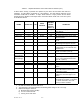
The plug-in amplifier module RF control and indicators, located in the center of the amplifier front
panel between the cooling fans, are shown in figure 3-1. The status and RF control functions are
described in detail in table 3-1. The alarms are described in detail in table 3-2.
Figure 3-1. G3S-1900-80 Amplifier Module RF Control and Indicators
Section
3