
User's Manual

044-05077 Rev. A
4-1
PRINCIPLES OF OPERATION
4-1. INTRODUCTION
This section contains a functional description of the multicarrier cellular amplifier.
4-2. RF INPUT SIGNAL
The maximum input power for all carrier frequencies should not exceed the limits specified in table
1-2. For proper amplifier loop balance, the out of band components of the input signals should not
exceed -40 dBc. The input VSWR should be 2:1 maximum (or better).
4-3. RF OUTPUT LOAD
The load impedance should be as good as possible (1.5:1 or better) in the working band for good
power transfer to the load. If the amplifier is operated into a filter, it will maintain its distortion
characteristics outside the signal band even if the VSWR is infinite, provided the reflected power
does not exceed one watt. A parasitic signal of less than one watt incident on the output will not
cause distortion at a higher level than the normal forward distortion (i.e. -65 dBc).
4-4. SYSTEM FUNCTIONAL DESCRIPTION
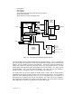
The G3S-1900-80 amplifier is a linear, feed-forward power amplifier that operates in the 60 MHz
frequency band from 1930 MHz to 1990 MHz. It is designed to operate in a maximum of two
continuous frequency blocks in the PCS band or an instantaneous bandwidth of 20 MHz. A typical
two-module system is shown in figure 4-1. The power output specification is listed in table 1-2.
Each amplifier is a self-contained plug-in module and is functionally independent of the other
amplifier module. The amplifier modules are designed for parallel operation to achieve high peak
power output, and for redundancy in unmanned remote locations. Each amplifier in the system can
simultaneously transmit multiple carrier frequencies, at an average total power output of 70 watts
(one amplifier module in a subrack unit) to 140 watts (two amplifier modules), with -65 dBc third
order intermodulation distortion (IMD).
The output from each amplifier is an amplified composite signal of approximately 80 watts before
combiner losses. All phase and gain corrections are performed on the signal(s) in the individual
amplifier modules. In a two-module system, the amplifier outputs are fed to a power combiner and
combined to form a composite RF output of up to 140 watts. Each amplifier module has an alarm
and display board that monitors the amplifier performance. If a failure or fault occurs in an
amplifier module, it is displayed on the individual amplifier front panel.
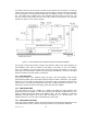
4-5. G3S-1900-80 AMPLIFIER MODULE
The amplifier module, figure 4-2, has an average output of 80 watts power (800 watts peak
power) with intermodulation products suppressed to better than -65 dBc below carrier levels. The
amplifier provides an amplified output signal with constant gain and phase by adding approximately
25 dB of distortion cancellation on the output signal. Constant gain and phase is maintained by
continuously comparing active paths with passive references, and correcting for small variations
through the RF feedback controls. All gain and phase variations, for example those due to
temperature, are reduced to the passive reference variations. The amplifier module is comprised
of:
Section
4