
Installation Instructions


044-05080 Rev. A 2-4
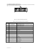
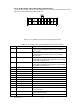
2-6. ALARMS AND SENSING CONNECTOR P2
The alarms and sensing connections on the amplifier are made through a 14-pin micro-fit connector
(figure 2-2) and are listed and described in table 2-2.
Figure 2-2. Alarms and Sensing Connector P2
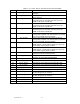
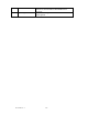
Table 2-2. Alarms and Sensing Connector P2 Definition
PIN SIGNAL DESCRIPTION
1 +5V_AIM 5-volt supply for the AIM; routed directly to the fan
assembly / AIM connector
2 +5V_AIM_RTN 5-volt supply return for the AIM; routed directly to the fan
assembly / AIM connector
3 +26V_ALARM 26V HPCA alarm input
4 +15V_ALARM 15V HPCA alarm input
5 REMOTE_SENSE Remote sense for HPCA; connected directly to 26V supply
6 REMOTE_SENSE_RTN Remote sense return for HPCA; connected directly to 26V
supply return
7 +5V_ALARM 5V HPCA alarm input
8 NC Not connected
9 26ARTN 26V alarm return connected to 26V return on the MCPA
10 ARTN 5V and 15V alarm return connected to 26V return on the
MCPA
11 +26V_FAN 26V supply for the fans; routed to fan assembly / AIM
connector
12 +26V_FAN_RTN 26V supply return for the fans; routed to fan assembly /
AIM connector
13 +26V_FAN
26V supply for the fans; routed to fan assembly /
AIM connector
14 +26V_FAN_RTN 26V supply return for the fans; routed to fan assembly /
AIM connector