
Installation Instructions


044-05080 Rev. A 2-8
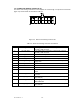
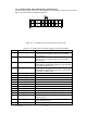
2-9. IIC, RS485, POWER, AND OTHER SIGNALS CONNECTOR P5
The alarms and sensing connections on the amplifier are made through a 18-pin micro-fit connector
(figure 2-5) and are listed and described in table 2-5.
Figure 2-5. IIC, RS485, Power, and Other Signals Connector P5
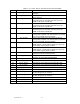
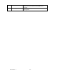
Table 2-5. IIC, RS485, Power, and Other Signals Connector P5 Definition
PIN SIGNAL DESCRIPTION
1 FORCE_ON+ Turns on LEDs (in the AIM) during power up sequence;
routed directly from MTRM connector to fan assembly /
AIM connector
2 FORCE_ON- Turns on LEDs (in the AIM) during power up sequence;
routed directly from MTRM connector to fan assembly /
AIM connector
3 +ALLOW_HPA_ENABLE Enables MCPA when high. Requires enable command via
RS485 and HW_ENABLE high impedance to ground and
no shutdown conditions exist.
4 -ALLOW_HPA_ENABLE Enables MCPA when high. Requires enable command via
RS485 and HW_ENABLE high impedance to ground and
no shutdown conditions exist.
5 MCPA_TX+ Differential RS485 link to MTRM
6 MCPA_TX- Differential RS485 link to MTRM
7 MCPA_RX+ Differential RS485 link from MTRM
8 MCPA_RX- Differential RS485 link from MTRM
9 IIC_CLK+ Differential IIC clock from MTRM
10 IIC_CLK- Differential IIC clock from MTRM
11 IIC_RX_DATA+ Differential IIC receive data (from MTRM)
12 IIC_RX_DATA- Differential IIC receive data (from MTRM)
13 IIC_TX_DATA+ Differential IIC transmit data (to MTRM)
14 IIC_TX_DATA- Differential IIC transmit data (to MTRM)
15 +5V_DC_IN +5V supply voltage for the IIC circuit on MCPA; not used in
any other circuits.
16 +5V_DC_RTN +5V supply voltage return for the IIC circuit on MCPA; not
used in any other circuits.
17 CABLE_DETECT Cable detect line connected to GPI/O port of MTRM